ALFOSC setup for polarimetry
Calcite
Mounting calcite plates in the aperture wheel
For imaging polarimetry only one calcite plate is
needed, the one labelled "Cal-90" on the holder but named "Calcite" in the
optical elements database. This is "Calcite 1" corresponding to optical
element ID 604. It is already correctly aligned in its aperture wheel holder
to take the orientation "Ver90", which splits the two components horizontally
on the CCD. (The 90 degree orientation of the calcite crystal is referred to
as Ver90, because angles are defined as polar coordinates, and the crystal
orientation is vertical when the target is split horizontally.)
It is per default mounted in the aperture wheel, preferrably in slot 0, where it is aligned at stepper motor position of 319000, which fits with the window
setting of polwin. (You have to unscrew all four screws and remove
completely the slitholder before you can mount the Calcite in its holder.)
Update with editsetup.
For spectro-polarimetry you need to mount another
calcite plate in addition to the one above. This one has a polarimetry slitlet
mounted on top of it, and its name in the optical elements database is either
Pol_1.0" (ID 508), Pol_1.4" (ID 509), or Pol_1.8" (ID 510),
depending on the slitlet. Per default the Pol_1.8" slitlet is used
(actual width is 1.5"), unless the observer wants a narrower slit.
When not mounted, this combined "Calcite + slit" item is found it the
Calcite plates drawer on the wall. It is already correctly aligned
in its holder to have the calcite in Ver90 orientation, as for the imaging
calcite. With the slit correctly mounted on top, the slit will be
horizontal, and therefore the orientation of the combined optical element
is referred to as "Horizontal" in editsetup and in the optical elements
database. This splits the horizontal slitlet horizontally, giving two
vertical spectra when used with the default vertical grisms.
Staff Instructions:
- Handle the calcite plates with care. They are very soft material and
should never be cleaned with any liquids nor rubbed in any way.
Remove dust
by a light blow of air only! Don't touch with fingers.
When they are not
mounted, the calcite plates are stored in their holders wrapped in optical
paper inside a plastic envelope in the Calcite plates drawer in the
filter carousel.
- This step is normally not needed. Both calcites should be correctly
and permanently mounted in their holders: But if you have to take the calcite plates out of their holders,
then check their orientation as follows. Use the piece of paper in the
calcite drawer of the filter carousel called: Calcite alignment tool,
which contains lines rotated by angles 0, 45 and 90 degrees. Place the
calcite plate (in its holder) such that the largest edge of the holder is
parallel to the lower line of the frame of the plot. If it is mounted
correctly, all lines will appear as double except for the horizontal one
(because it is displaced horizontally). If this is not the case, then
loosen the inner tube by unscrewing the screw holding the tubes together
(need a small hex key), and correct the alignment.
NB! It is crucial that the two calcite plates are both oriented in exactly
the same way (i.e. not even 180 degrees offset), otherwise the slit
aquisition for spectropolarimetry will not work. If you have to rotate
the calcites, keep this in mind, because the access to the actual calcites in
their holders is opposite for the two holders! One you operate from "above"
and the other you operate from "below". NB!
- Normally we use the Pol_1.8" slitlet and this one is installed
by default and aligned, and you do not need to read further on this step.
The polarimetry slitlet is mounted on top of the calcite plate
(on the side where light enters from the telescope), and is fixed to the
calcite plate holder by tape. Align it by looking through the calcite at
the slit, which now will appear as two slits horizontally offset to each
others. Look directly at the calcite such that you see your eye reflected
in the center. The slit is aligned with respect to the calcite plate when
the two slit images are on a line. See below for aligning the slit with
respect to the CCD.
- Mount the calcite with the slit in the aperture wheel. You have to
unscrew all four screws and take out the the whole slitholder. (Take care
that screws don't fall into the instrument!)
- Update the ALFOSC aperture wheel content using the program
editsetup as user obs on selena. Note that the 3 polarimetry
slitlets when used on top of the Calcite are named:
Pol_1.0", Pol_1.4", and Pol_1.8". In
the database they can have orientation either vertical or horizontal. NB!
As from April 26th 2012 they should always be installed horizontally!
This also means that for spectro-polarimetry you can use grisms in their
default vertical orientation.
Aligning the polarimetry slitlet with respect to the CCD:
- Put the polarimetry slitlet in the beam and set all other positions
to open.
- Run alfosc.focus-offset. This sets the internalt focus to
870 units less than the default value for ALFOSC which is
1610.
- Turn on the ThAr lamp in the ALFOSC calib unit.
- Make a small window by typing alfosc.polwin.
- Take a test image with exp 1 and use imexam to
find the y-position of the left and right parts
of the two slitlets split by the calcite. Measure the two y-positions with
the key 'k' and determine the difference dy.
- If the slit is tilted, change the encoder position of the wheel in
the program editsetup and iterate until the slit is aligned.
About -1400 units is needed to rotate the slitlet clockwise by an amount
corresponding to dy = 3 pixels from left side of left slit to right end
of left slit. (For reference: when mounted in aperture slot 6 the
best alignment was found at encoder value 237200.)
- When the slit is aligned, type resetxy and take a full
image to determine the slit position, i.e. the center
of the left image of the slit, in order to update the file
~obs/alfosc/slitpos.def.
NB! Note that both the X and Y values need to be edited!
Instruct the observer to use the left image of the target for slit
acquisition.
- Make an appropriate window for spectroscopy for the user by setting
xbeg, ybeg, xsize, ysize in a script, such as for instance (and always in
this order), and store it in the script directory of the observer:
#!/bin/tcsh
alfosc.resetxy
alfosc.readspeed 200
alfosc.xsize 250
alfosc.xbeg 1150
alfosc.ysize 1350
alfosc.ybeg 1
alfosc.bin 2
The above is an example for Grism#10 where the upper part (showing the
zeroth order) has been cut. Depending on the grism, you might wish to
keep the full size in the vertical direction.
Retarder plates
lambda/2
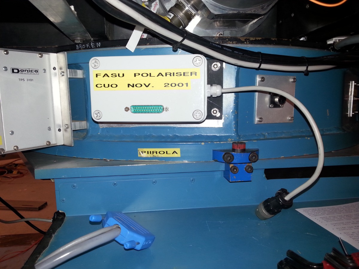
The idea is that FAPOL will always be mounted in FASU and the default
retarder plate is the 1/2 wave plate (lambda/2), which is used to
measure linear polarimetry.
When the lambda/2 is correctly mounted in FAPOL, as described below,
its optical axis is at 0 degrees with respect to the principle plane
of the calcite crystal. The orientation of the lambda/2 is not very
critical, however, as the zero-point correction of the angle can be
found with high-polarisation standard stars.
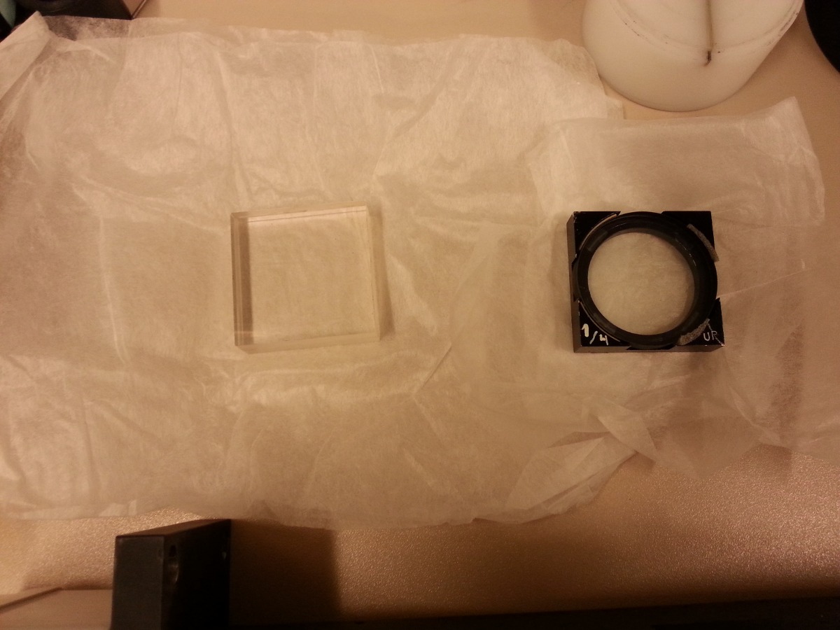
lambda/4
In order to measure circular polarimetry, the 1/4 wave plate
(lambda/4) has to be installed. (Note that it is possible to measure
simultaneously circular and linear polarisation with the 1/4 wave
plate, but at a cost of 50% efficiency for the linear mode.)
When the lambda/4 is correctly mounted in FAPOL, as described below,
its optical axis is at 45 degrees with respect to the principle plane
of the calcite crystal, that is the plane defined by the o- and e- rays.
Mount lambda/2 or lambda/4 in FAPOL
If you have to change plates, make sure you handle them with care.
These plates are expensive. They are located in the their
marked boxes in the cupboard above the filter table in the electronics
room.
- Make sure the FAPOL carriage is out of the beam.
- Power off the FASU controller.
- Remove the round connector from FAPOL.
- Disconnect the DB25 connector.

- Unscrew the 4 screws that mounts FAPOL in FASU. The unit is heavy
and will fall down a few mm if not held.
- Slide the FAPOL unit carefully out of its hole and take it down
to the control room.
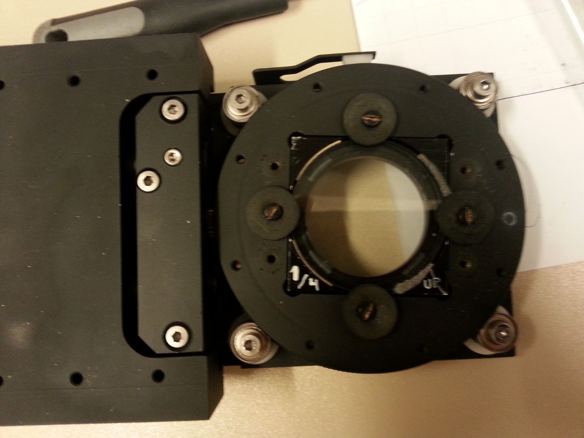
- Sit at a table and carefully unscrew the 4 screws with rubber
washers that hold the retarder plate in place. Align the 1/2 wave
plate such that the red pen mark aligns with the white zero on the
holder. The arrow points to which side is up. Both the 1/2 and
the 1/4 wave plate should be mounted such that the circular mark on
the plate holder points to the circular mark on the carriage (which
is at the outer end of the carriage).

- For the 1/4 wave plate fix one screw per side of the plate.
For the 1/2 wave plate two screws on two opposite sides is the best way.
- Take the unit back, slide it in and fix it, connect the cables
again and power on the FASU controller. Don't forget to open the
FASU shutter.
- NB! Remember to use 'editsetup' so the UIF knows which plate is in
and the FITS headers become right! See below.
Changing the setup information for the retarder plate
-
Use
editsetup to update the name of the mounted retarder plate.
- Do 'shutdownobssys alfosc'.
- Do 'startobssys alfosc'.
Physically mounting the FAPOL unit on FASU
- There is a 13 mm gap between the top side of FASU B wheel and the underneath
of the FAPOL unit. FASU filter holders stick out about 2mm above the wheel. To be
conservative, don't put in thick filters in FASU B which will protrude more
than 9mm out of the filter holders.
- Power off the FASU controller.
- Remove the black plate that is facing towards the staircase.
- Mount FAPOL in the hole and fasten it with the screws.
- Remove the blind round connector to the right of the hole.
- Connect the round connector from FAPOL to the connector to the
right of the hole.
- Connect the DB25 connector to the FASU controller.
- Power on the FASU controller (Don't forget to open the shutter).
Connecting FAPOL on a normal instrument mount
- Connect the network cable to the network switch mounted on the adapter.
You can use whatever port you like.
- Connect the 220V cable to a 220V outlet.
Misc
Start of the control programme
The control programme for FAPOL is started from any of the lisa X-terminal
windows by giving the command (logged in on sandra):
- /usr/local/bin/fapo-control
Since February-2007 FAPOL starts up together
with the rest of ALFOSC. If for some reason it doesn't, then check the
processes and kill all old FAPOL processes that might be running. Start
up FAPOL manually with the above command
Note that after having moved the calibration mirror, it is normal that FAPOL
initializes when you command carriage to go in. The initialization should
take about 10s, and the total time to get FAPOL in is about 40s. If it hangs,
then interrupt the FAPOL s/w by CTRL-C and power cycle the FASU controller
(remember to open the shutter afterwards). Restart FAPOL s/w.
16 retader plate positions
- For testing purposes there are 16 retader plate positions available
(the step size is 22.5 degrees). Non-UIF positions are not updated in
the UIF, i.e. the retader-plate might have different position than
the UIF indicates, however the FITS-headers are updated in a correct way.
The use of the "hidden" positions is the normal FAPO-script
way e.g. "!fapo-112.5" etc.
Comments on previous orientations of the Calcites
Current status: Since April 26th 2012 the two calcites
are again mounted at 90 degrees orientation in their holders. This means that
the beam is split in two orthogonally polarized components horizontally on the
CCD. (NB! Note that in the optical elements database the 90
degree orientation is referred to as Ver90, because angles were defined as
polar coordinates.)
For spectropolarimetry the horizontal slit is displaced horizontally
giving two vertical spectra.
Old setup info: From April 2003 to November 2008 the
two calcite plates were mounted at 90 degrees orientation in their holders.
This way the slit was horizontal and spectro-polarimetry done with grisms
in the vertical (default) orientation. From November 2008 to April 2012
the calcites were mounted at a 0 degree orientation of the calcites, splitting
the beam in two orthogonally polarized components vertically on the CCD,
needing the slit to be vertical and the grisms horizontal! This was done to
reduce the readout time for fast spectro-polarimetry. With the arrival of the
new ALFOSC controller in June 2012 there was no longer a speed issue, and it
was decided to go back to the old setup, where the (default) vertically mounted
grisms could be used.
Comments to Anlaug Amanda Djupvik
|