Some known CCD3-controller features
- Structure in x-direction seen especially in bias (full) frames.
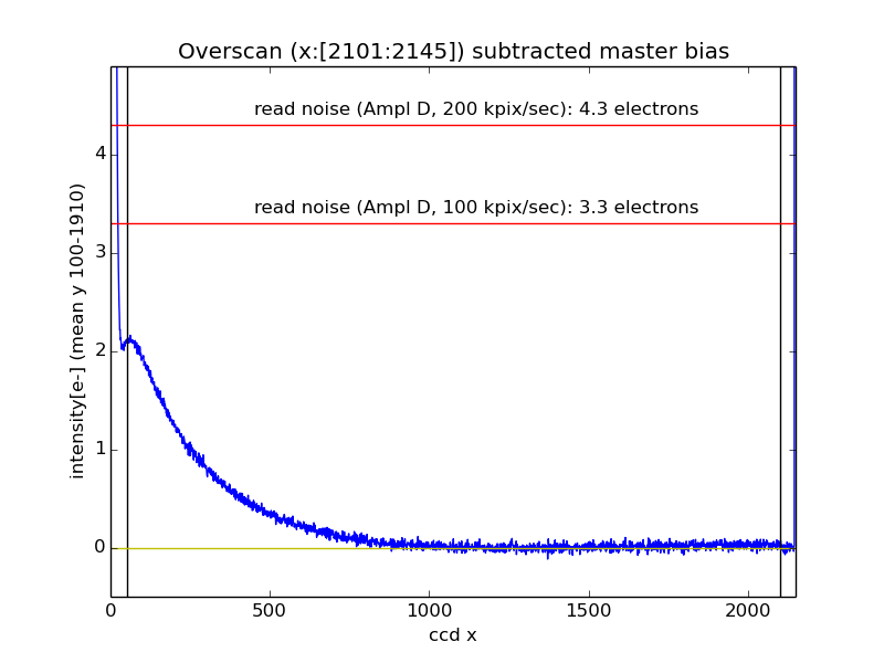
The average column of a combined master bias frame. The master bias was combined
from 11 frames using iraf/zerocombine. The vertical black line indicates
prescan and overscan region, red horizontal lines show the read noise
for a given read-out-speed and the yellow line (zero) is to guide eye.
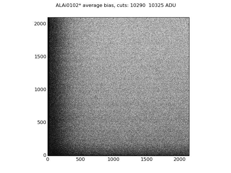
Bias structure
The bias structure is slightly different if only a portion (in x-direction)
has been read out.
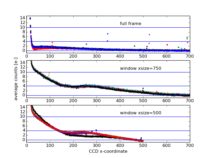
When reading only a window a few electron gradient is expected to be seen.
However the structure appears to be stable.
The "full frame" plot shows 24 bias frames,
"window xsize=750" 14 and "window xsize=500" 17 frames
(however see below about "window xsize=500").
Window the first pixel in x
As shown above the "window xsize=500" appears to have variable
bias structure.
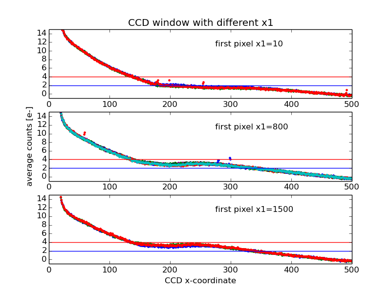
The above plot shows the bias profile when the position of the window
has been moved from left to right.
The profile in x-direction is almost identical when the first pixel
is either 800 or 1500, however for the x1=10 window the profile
is clearly different. This can be seen also from the "bias structure plot"
(above).
Overscan stability
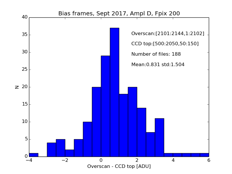
The overscan and the imaging area follow normally each other accurately.
For example selecting 188 bias frames from September 2017
the difference between the right hand side overscan and the top
of the imaging area show median difference of 0.8 ADU.
Occasionally there is also a gradient in y as well
however the overscan follows this as seen in the figure above (full
frame including the overscan).
If the detector is exposed with bright light, for example when installing
grism (the dome lights are switched on),
a bias frame taken few minutes after has a visible gradient
in y-direction imaging area, x-overscan areas are clearly visible,
while the x-overscan has no gradient.
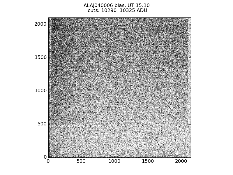
It takes about 40 minutes to stabilise the bias level.
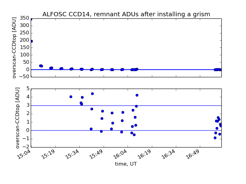
Test data (ALAj040001-49): open the ALFOSC grism/filter wheel cover
(while the dome lights were on) and after that taking sequence of
three bias frames followed by five minutes waiting.
FITS headers
- EXPTIME: Shutter correction is not included to the vale.
The correct exposure time is is about 0.1 seconds longer than
the requested time.
- BIASSEC value ('[3:52,1:2102]') is for the CCD#8
- TRIMSEC keyword is missing
- CCDSEC keyword is missing
- DETSEC keyword is missing
- CCDTEMP (Detector temperature) units are missing
- LN2TEMP (LN2 temperature) units are missing
- P_DEWAR (Dewar pressure) units are missing
- The keywords CCDTEMP,LN2TEMP,P_DEWAR have unreliable readings
- FITS-header CRPIX1 and CRPIX2 have wrong values in windowed image
see FaultReport 2762
- Some times WCS-keywords (CTYPE1,CTYPE2,CRVAL1,CRVAL2,CUNIT1,CUNIT2,
CRPIX1,CRPIX2,CD1_1, CD1_2 ,CD2_1, CD2_2) are not written in HDU1
- Some times only mandatory keywords are present
- GAIN Fixed 19.4.2017 Ampl D (value 0.33 is for the CCD#8)
|