![]()
![]()
![]()
![]()
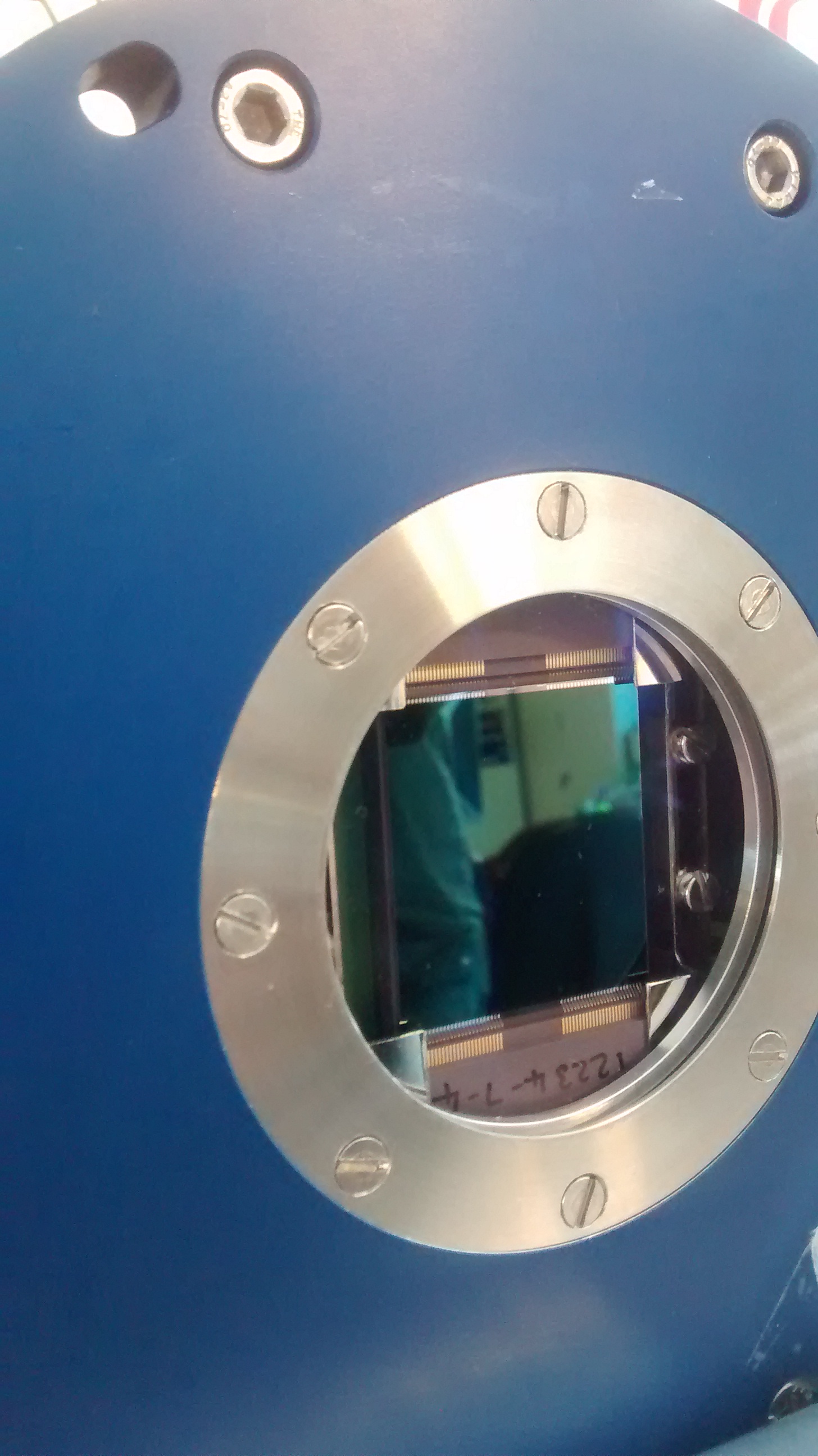
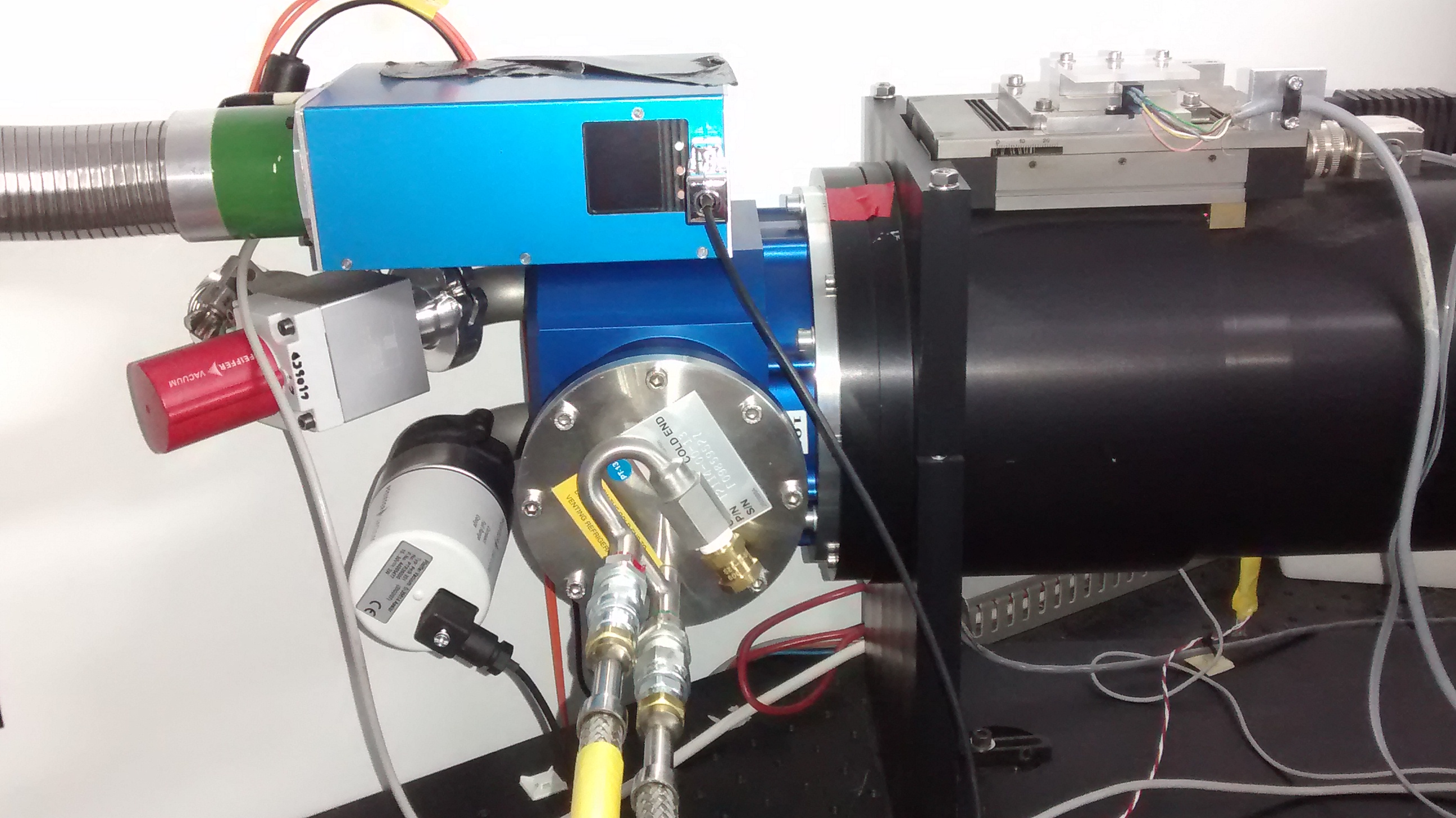
Commissioning of the new CCD15 for FIESOn 30/9/2016 we installed the new CCD15 onto FIES. New vacuum ducting was installed to allow for pumping from the front-room while the CCD is on FIES. The new CCD comes with a new controller, and the current detector+controller setup for FIES is now very similar to that of ALFOSC+CCD14, with similar readout times and characteristics.CCD15:CCD15 is a deep-depleted CCD from E2V, with fringe suppression, with, in comparison to CCD13, improved QE in the red, and somewhat less QE bluewards of 400nm. The pixels are 15 microns large, and consequently the CCD is about 10% larger than the previous one. This allows to sample further into the infrared part of the echellogram, and we now reach from 3700 to 9100 Angstrom for the high-res fiber (F4), while for the other fibers we sample few hundreds of Angstroms less into the IR. For the previous CCD the sampled range was 3700-7300 Angstrom.With CCD15 there are small gaps in wavelength coverage between the reddest few orders, i.e. for wavelengths larger than 8300 Angstrom. The high-res fiber's range extends to 9100 Angstrom only if you are happy to extract the reddest order that is partially clipped by the edge of the CCD. It is clipped at the center of the blaze, away from the blaze the curvature brings it back onto the CCD. See the table below for wave ranges sampled by the individual fibers.
Controller and main read-out characteristics:The new controller allows for faster readout (50 sec in default read speed, versus 90 s for CCD13), while the best achievable read-out-noise (3.3 e-) is a bit worse than for the old CCD13 (2.8 e-).For CCD15 with the default amplifier B and default read speed (108 kpix/s) we now have: RON=3.3 e-, gain=0.142 ADU/e- , linear to within 0.5% between count levels of 1000 to 160000 e-.
Bias level and structure:Although there is little high-order structure in the bias level we have found there is a variable slope in the Y direction. This slope can be seen in and modelled for the wide X underscan region.The typical bias level is around 10000 ADU. For B amplifier, the pixels in the high-X overscan region are affected by bias structure ramping up to the right-most pixels. These are closest to the read-out register B.
Overexposure:The new controller reads into 4-byte pixel values, which means that the 65000 ADU counting limit does not exist any longer. The pixels can be exposed upto the full well linearity limit, which is about 160000 e- or 1.1M ADU.
When overexposing more than the linearity limit, we see three features appearing,
listed below in order of increasing overexposure Overexposure should not happen on stellar frames, unless stars brighter than 4th magnitude are exposed for a long time. The halogen flat-field exposures are kept well within the linearity limit when using easyhalo and fies-calibs. The bright red Argon lines in the ThAr exposures will always lead to overexposure, even when exposing to the standard level using easythar. For this reason we have chosen to build into the expose and dark commands a cleaning procedure (remove_remnants) that clears the CCD in only 3.5 seconds before the requested exposure. This procedure only removes the remnants in the image following the overexposed one. This procedure does not get rid of the horizontal banding and vertical blooming in the overexposed image itself.
Cosmic rays:As the deep-depleted silicon is more prone to pick up cosmics, we advise our users to consider to split up long exposures (e.g. longer than 20 minutes) in to two or three shorter-exposed ones, in order to better account for the cosmic ray hits. Not only are there more hits, they also appear with longer streaks on the CCD.
Echellogram orientation:With the default amplifier B, the read-out orientation of the echellogram is the same as for the previous CCD: blue is on the left and at the top.We have 100 pix X underscan, 50 pix X overscan, 38 pix Y overscan. Furthermore the first and last few rows are affected by 'edge effects' and may be stripped from the useful CCD region.
CCD15 PSF:For the high-res fiber the ThAr lines have FWHM=2.0 pixel in the spectral direction over a large portion of the CCD, resulting in a spectral resolution of R>65000.In the cross-dispersion direction the FWHM of the echellogram-order profiles is larger than 4 pixels on the blue side of the CCD going down to FWHM=3.6 pixels for the reddest orders.
Fringes:The excellent fringe suppression of the new CCD results in that we do not find any fringes short of 8000 Angstrom, and have a peak-to-peak fringe amplitude around 5% at 9000 Angstrom.
FIEStool:Our reduction tool is being upgraded to handle the new CCD features. Until then the online FIEStool is switched off. We will run all FIES frames obtained so far with the new CCD through FIEStool once the updated version is available.
John Telting |