Description of basic differences in BIAS and NOTCam BIAS
Jens Klougart, NOT, Apr. 2006
1. Introduction
The data acquisition software, BIAS, was originally written for "normal"
CCD operation, and modified several times for operating a number of different
chips, with different features and from miscellaneous manufacturers. The
software controls the BroCam CCD-controller, and gives the user the ability
to perform a large number of exposures, readout modes, and some basic
operations on the images.
With the 1K x 1K Hawaii Infrared Array (hereafter HIA), the control from
both the CCD-controller and the BIAS software is quite different from that
of a "normal" CCD. The controller, with its build-in firmware, was heavily
modified, and the control and the readout modes were changed to accommodate
the HIA. This also had implications for the BIAS software, and extensions
were written. A number of commands for CCDs also had no meaning, and were
removed.
2. Important changed issues
These very basic commands have been changed significantly:
- expose (exp)
- mexpose (mexp)
- dark
- mdark
and 2 new HIA specific commands were introduced:
- frame (fra)
- dframe (dfra)
There are no commands for geometry setting and binning, focus exposures
and for controlling integration times (commands: readout, hold, resume
and addtime). Some other CCD specific commands are also removed.
Unfortunately the abort command was never made to work!
3. The (most) important changed commands
An essential issue in HIA is the ability to do non-destructive readout,
and that every exposure/readout is started with a reset-image.
- expose, dark
- mexpose, mdark
- frame, dframe (new)
- clear (new)
Except for opening and closing the shutter, these commands work the same
4. Single shot mode, reset-read-read (Fowler sampling)
The commands are:
- exp ttt.t Do one ttt.t second exposure
- dark ttt.t Do one ttt.t second exposure, with shutter closed
Just before the start integration command (@SINT) is sent to the
controller, the PCs CPU time is recorded for later incorporation in the
FITS header. The operation sequence is as follows:
- Record PC (Linux) time and date for TM-START
- Send start integration
- Controller sends the reset image, takes 3.6 sec, BIAS receives
- Controller starts exposure timer
- Controller opens shutter if command was exp
- Wait for exposure timer to end
- Controller closes the shutter if command was exp
- The exposure image is sent to the PC, takes 3.6 sec
- BIAS recognizes the receival of the last line, updates ds9
- Record PC (Linux) time and date for TM-END
- Images are reorganized to: (image - reset), reset
- The 2 images are stored in a 3 dimensional FITS file, 1024x1024x2
Comments: The total time of the command should be: 2 x 3.6 sec +
exposure time + the time for storing, postprocessing, updating ds9.
A little additional time can though be foreseen due to the fast data rate
from the controller (approx. 5 Mbit/s) in correspondence with the bandwidth
of the PC's ISA bus. The setup here at NOT also might give a small timing
penalty, as it is known that ds9 (written in Tcl/Tk) has a very conservative
interface to X11, specifying a total update of frames (Tcl/Tk-frames) on
many called functions. This is especially time consuming, when the
X11-display is not running directly on the BIAS-PC.
5. Multiple single shot mode, reset-read-read (Fowler sampling)
The commands are:
- Record PC (Linux) time and date for TM-START
- Send start integration
- Controller sends the reset image, takes 3.6 sec, BIAS receives
- Controller starts exposure timer
- Controller opens shutter if command was exp
- Wait for exposure timer to end
- Controller closes the shutter if command was exp
- The exposure image is sent to the PC, takes 3.6 sec
- BIAS recognizes the receival of the last line, updates ds9
- Record PC (Linux) time and date for TM-END
- Images are reorganized to: (image - reset), reset
- The 2 images are stored in a 3 dimensional FITS file, 1024x1024x2
- If less than n integrations have been performed, go to 1.
- Calculate: MeanImage = SUM( image[n] - reset[n] ) / n
- Display the MeanImage in ds9.
- The MeanImage is stored in a 2 dimensional FITS file, 1024x1024
(TM-START and TM-END is the same as for the last (nth) exposure,
a new FITS keyword NCOMBINE=n is added.
Comments: The total time of each exposure should be: 2 x 3.6 sec +
exposure_time + the time for storing, postprocessing, updating ds9.
Each FITS header in the multiple exposures has the FITS keyword
EXPMODE changed from only showing the given command, to
also showing the number in the series, f. inst:
Meaning it is no. 3 in the series of 10.
The last part of the comment concerning timing above also applies here.
The storing of MeanImage might be taken away !!
Note that the difference between mexp/mdark and doing a number of
f. inst.
in a batch file, is that doing it in a batch file, it is executed as given
the single exposures. The command interpreter is entered every time, and
the total controller setup is done. This will have implications on the
timing. The next multiple exposure is started immediately after the FITS
file is stored. Also no MeanImage is calculated.
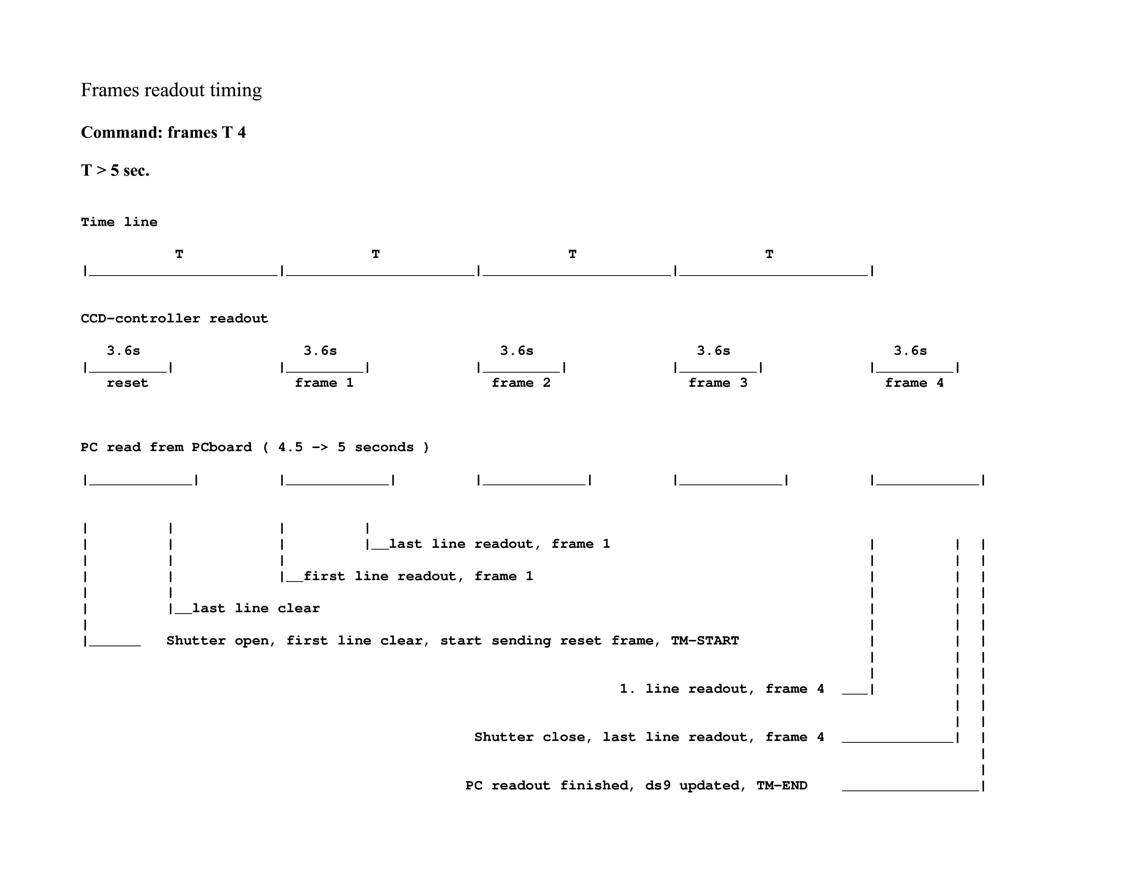
6. Frames mode, ramp-sampling mode
Frame mode is special to the HIA. Due to the non destructive readout of the
array, multiple image readout while adding electrons on the array is possible.
There are 2 commands:
- frames ttt.t n
- dframes ttt.t n
The first one exposes with the shutter open, the second one with the shutter
closed. These commands read out the array n times while exposing,
the time between each read being ttt.t seconds. The total exposure
time is ttt.t x n seconds.
n can due to memory limitations at most be 14.
Due to the readout time of 3.6 sec, ttt.t must be larger than 3.6
- Set an image counter = 0
- Record PC (Linux) time and date for TM-START
- Send start sequencing
- Controller opens shutter if command was frames
- Controller starts exposure timer
- Controller sends the reset image, takes 3.6 sec, BIAS receives
- Wait for exposure timer to end
- If the image counter < n, restart timer
- The image is readout non destructive and sent to the PC, takes 3.6 sec, BIAS receives, ds9 updated.
- If the image counter < n, increment image counter, go to 7.
- Controller closes the shutter if command was frames
- BIAS now holds 1 reset image and n exposure images
- Record PC (Linux) time and date for TM-STOP
- A linear regression of each individual pixel is done fitting a
straight line through all images (not reset subtracted), also the
reset image. A new image is created. The algorithm is shown below.
- The data buffer is reorganized to hold:
lin-regr, (image[1]-reset), .... (image[n]-reset), reset
- Images are stored in a 3 dimensional FITS file, 1024x1024x(n+2)
Comments: The last part of the comment concerning timing above also applies
here. Frame command with integration time < 5 sec have a delay in
the readout from the interface board, but the timing of the exposure and
readout in the controller is correct. This will result in a TM-STOP in the
FITS header which is larger than ttt.t * n + 3.6sec.
This means that the PC is behind the readout from the controller,
but will catch up after the last image is readout. The actual mean
(center pixel in all 4 quadrants) TM-START of the command is therefore
TM-START+(3.6/2) for the reset image, and TM-START+(3.6/2)+( (n+1) * ttt.t)
for image no. n. (see the timing diagram in section 10).
7. Linear regression
A final image is calculated, fitting a straight line through the same pixel
in each image, including the reset image. The resulting image stores the
slope of this line, multiplied by n.
The method used is doing linear regression, using least square method. The
method is described in "Numerical recipes" pg. 504-505. The uncertainty
(or weight) used here is equal (= 1) to all images. Below is a listing of
the C-function with some comments (more comments than in the actual source
file). Unfortunately the initial formulas were taken from another source,
giving different variable names.
The array and buffer manipulation might be a bit cryptic, but all images
are held in one large buffer, which has the size: (1024*1024) * (n+2),
"+2" is one extra image for the reset image, and one for the resulting
calculated image. At the time of the programming, it was essential for
speed to address arrays using variable pointers, incrementing them when
accessing the arrays in a linear manner.
8. Miscellaneous
The imexamin aperture text output will show FWHM for both the WF-camera
and the HR-camera.
A new clear command is introduced. It issues actually a dark 0
to the ccd-controller, the reset image is sent to the PC, but not the actual
image. This command takes 3.6 sec, and no processing of any data is done.
This is especially useful, if the array has been saturated.
9. Code for the linear regression calculation
Extra commented and cleaned up function listing. See the code
here.
10. Timing diagrams.
Two timeline diagrams are presented as examples of the ramp-sampling mode.
They describe the exposure command frame t 4. The first diagram is
for t > 5 seconds, and the second is for t < 5 seconds. See the text under
section 6 for details.
frame t 4 with t > 5
frame t 4 with t < 5
NOT, Apr. 2006
Jens Klougart
|
