Transfer from Service Building
From Service Building to the dome:
This checklist assumes that the Closing and pumping
checklist has been completed, NOTCam is evacuated, firmly attached to
the white frame on which the motor and detector controllers will be mounted
and which is still attached to the blue lifting table in the service
building.
- Print a copy of this checklist and check off each item as it
is completed.
- Close NOTCam vacuum valve. The valve is a big black knob which needs
to be rotated several (7) turns.
- Close pump valve. The valve is a white knob which should be turned
180 degrees (this goes in a few steps).

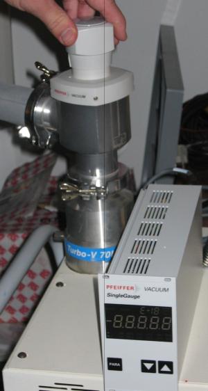
- Stop pump, and disconnect from dewar. Power off and remove the pressure
sensor display (disconnect cable from sensor) since you will need it
in the dome.
- Turn the motor controller OFF and disconnect the cables that
run from the controller to NOTCam (disconnect them where they
are attached to NOTCam).

- Stop the temperature/pressure logging as instructed in
the monitoring page.
- Disconnect and wind up the network cable that connected the motor
controller with the network and place down the left side of the
large workbench.
- Connect the normal serial cable to the motor controller, just so we
don't loose it!
- Make sure all nuts (~32) holding the NOTCam lid are properly tightened.
- Move NOTcam to the mechanical workshop and mount the blue adaptor flange
plate on NOTCam:
- Make sure the cross with the lifting ring is still fixed to the adaptor
flange properly (according to marks).
- Install a wire with integral bolt to the topmost mount hole in the
adaptor flange. There is a wire large enough to accomodate the
hand crane hook.
- Using the orange hand-crane, lift the adaptor flange.
It should be hanging vertically in the orientation suitable for attaching
to NOTCam in its horizontal position.
- Bring the flange up to NOTCam then tighten the wing nut on the side

to ensure correct alignment and bolt it on using the large,
black-anodised tabs and their accompanying hex-bolts.
The tab under the dewar is held on by a normal hexagonal-ended bolt.
Note the red felt-pen marks for alignment, and the gap information
written on the vessel.

- Unhook the hand-crane from the eyebolt in the adapter flange.
- Unscrew the 4 long screws which fix NOTCam to its table.
- Park the pick-up outside the workshop and put the large piece of plastic
white foam in the back.
- Fix NOTCam to the orange hand-crane.
Do not use rope. There is an eyebolt, with removable bolt,
large enough to accomodate
the hand-crane hook. It should still be attached to the instrument.
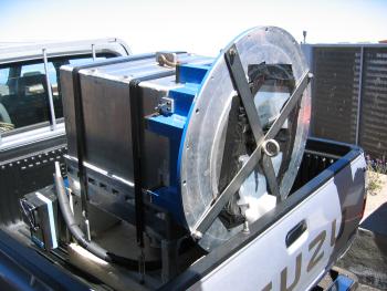
- Slowly and carefully move NOTCam onto the back of the pick-up, squarely
on the white plastic foam.
- Secure NOTCam on the pick-up using the broad yellow strap and cinch,
which is usually kept in the back of the pickup.

- Drive sloooowly to the dome.
- DO NOT PARK THE PICKUP TRUCK INSIDE THE SAFETY CHAIN UNTIL
THE TELESCOPE IS IN HOIST POSITION!
- Power-ON telescope.
- Go to hoist position.
-
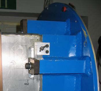
Set alt 90 on the TCS, and if possible insert the
telescope altitude locking pin (behind FIES).
- Power-OFF the telescope.
- Hit the emergency stop button on the dome floor
- Remove the safety chain outside and reverse the pickup truck so
that NOTCam is placed immediately under the hoist hook.
- Lower the hoist from the dome floor.
- Fix NOTCam to the hook using only the eyebolt with removable bolt which
you used to move NOTCam with the orange hand-crane.
- Lift NOTCam by slow speed only up to the dome floor.
If the instrument starts to oscillate vertically, even slightly, then
STOP and wait for the oscillations to stop before continuing.
Under these circumstances, NOTCam is bouncing up and down on the
chain, stretching it slightly. Given that the instrument weighs about
200kg and the hoist is specified to carry 500kg max, these
oscillations could break the chain if allowed to continue.
- Move the pickup truck and replace the safety chain outside.
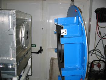
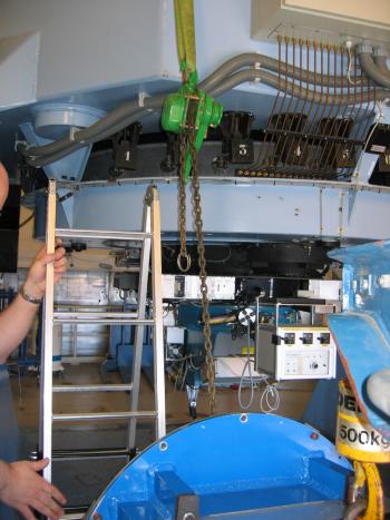
- In the dome move the hoist with the instrument hanging from it towards
the telescope structure.
- Fix the green hand-winch to the telescope structure, with one of the green
straps (folded double), by the eye tab(the one closest to the hoist)
used to hold the primary mirror
when it is removed for realuminising. Both the green hand-winch and strap
can be found next to the hoist.

- Attach the hand-winch hook to the cross-fitting mounted on the front
of the adaptor flange.
- Lift the front face of NOTCam with the hand-winch while
gently letting out the hoist chain so that the instrument rotates
by ninety degrees until the window is facing upwards and the full
weight of the instrument is taken by the hand-winch.
- Detach the hoist from NOTCam.
- In this turned position, lower the instrument onto its trolley.
- Detach and remove the hand-winch.
- Dismount the lifting cross and store behind the right-hand metal
cupboard on the observing floor.
- Place the NOTCam window-protector.
- Reset the emergency stop button.
- Power on the telescope. Set alt 90 and if the locking pin was used
remove it from the telescope.
- Check the pickup has been moved then on the TCS go to zenith position,
return to park position and power-off the telescope.
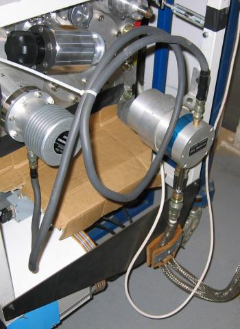
- Mount the PTR rotary valve and tubes support bracket on to the
NOTCam white frame, then if fitted remove the dust cap from the end
of the PTR tube and put in the cardboard box in the
right-hand cupboard.

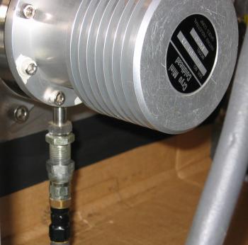
- Connect the tube to the head, if necessary refer the instructions in
the manual that's kept in the right-hand cupboard on the dome floor,
with Pluse Tube Cryocooler (PTC) on the front page. Following the
instructions in the manual, look at the drawing on page 11, and use
the proper tools lying near the manual. Place tube vertical in line
with the mounting piece, and turn the knob by hand as long as it goes
easy, while holding it straight. Then use the tools and tighten
quickly (in order to minimize helium leakage) until fully connected.

- Mount the motor controller to the frame, three bolts at the top and one
at the bottom.
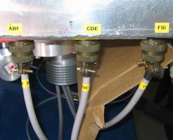
- Connect cables.
Three round green motor connectors, one smaller green
temperature sensor conector, pressure sensor and shutter cables. Also
don't forget to connect the orange network cable (rolled where the
Stancam PTR hoses goes into the telescope base) to the small black box
called 'NPort 5210'.
- Make sure that the array controller is switched off.
Connect the power cable from the power bar to a 220V socket.
- Turn on the motor controller to check the vacuum.
- Connect the pressure display to the pressure sensor on the pump.
- Connect the pump and continue pumping.
- Open the vacuum valve on the pump and start the pump.
- Wait until the pressure at the pump is approximately 1 decade better
than the instrument then open the NOTCam vacuum valve.

- Refer to the monitoring page to
start again the NOTCam log-analyzer program.
|