NOTCam Array Electronics upgrade Dec 2007
The purpose of upgrading the array electronics was to get rid of the "dark current"
problem, i.e. the fact that the measured dark counts are much higher than expected,
and the strange behaviour where the dark images have less counts the longer(!) the
integration time is ...
The electronic upgrade consisted in exchanging the printed circuit board (PCB) to
which the array is connected with an upgraded PCB with recommended voltage settings
(from Rockwell) for the Hawaii arrays. The main difference between the old and the new
electronic configuration is that while the old setup had no "biasgate" voltages set,
the new setup allows the user to adjust these around a default recommended value of
3.5V.
On the 3rd of December 2007 the new PCB was tested out with the engineering grade array
cold. The QC for the ramp-sampling mode was run for two different values of the
biasgate voltage (default=3.5V and max=3.8V), but it was not possible to do further
tests because of a serious problem with the vacuum of the cryostat. (Also, it was
not possible to have the QC analysis updating the web because of the web server
swap at these dates. We can re-run this and get the plots on the web.)
No major difference was seen between the old and the new PCB from the QC results.
The gain was around 3.2 e-/adu and the ron was at 13 e- for the ramp-sampling mode.
The 1% linearity limit was at 17000-24000 adu. Also, no obvious undesirable effects
were found with the new PCB. But apparently the upgrade did not cure the dark
current problem: Still the the measured counts on darks were too high and the
behaviour vs. exposure time as before, i.e. many counts on short darks and less
counts on longer darks.
In the following we describe the differences between the old and the new PCB as seen
on the engineering grade array.
We also compare the behaviour of the new science array with the old arrays.
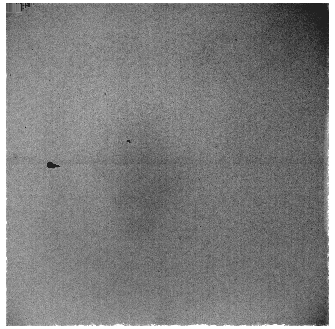
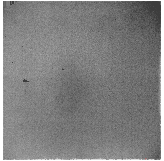
Darks
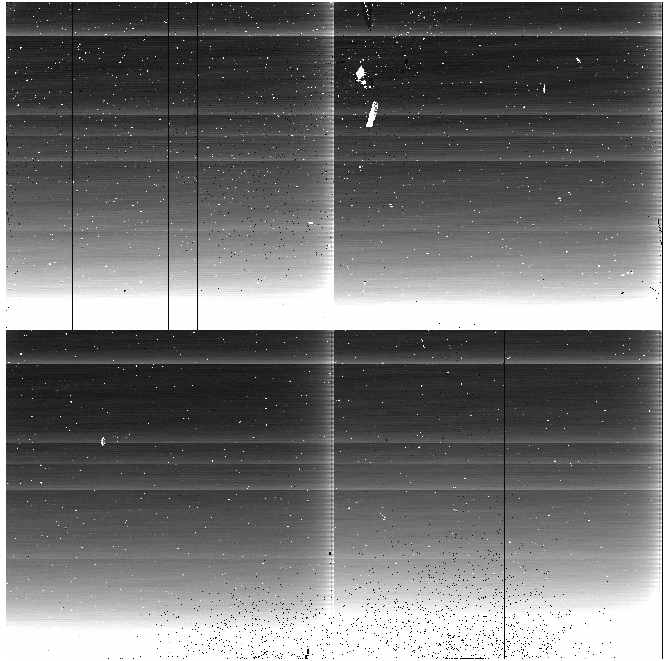
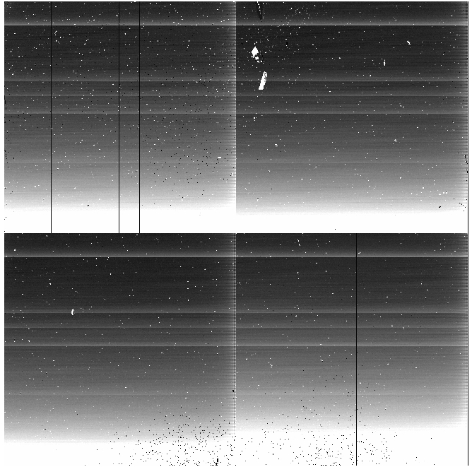
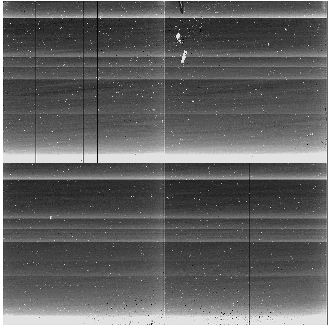
Engineering array "dark 0" images from left to right: 1) new PCB (biasgate voltage
set to default=3.5V), 2) new PCB (biasgate voltage set to max=3.8V), and 3) the old
PCB where we could not adjust this value.
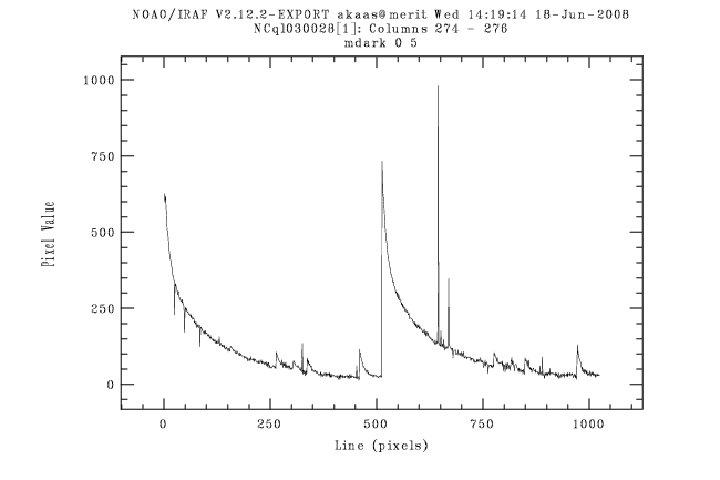
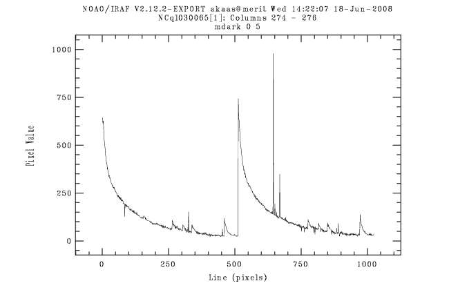
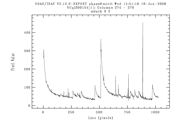
Vertical cuts through the above images at x=274-276 averaging over 3 columns.
Notes on darks:
- The vertical cuts show a high intensity ramp in the first readout lines per
quadrant. This effect, called the "dc-gradient", has its origin in the "reset anomaly",
the fact that the integration ramp has a nonlinear initial part after a "reset" of the
detector.
- For the old PCB the ramp starts at 300 adu and levels off at about 50 adu on a
"dark 0", while for the new PCB it starts at 600 adu and levels off at 50.
- The vertical cut shows the same type of profile in every 512 pixel quadrant. Apart
from the steep ramp from pixel Y=1, there are also smaller jumps at Y = 156, 264, 304,
337 and 460. The jump positions are exactly the same for each quadrant. The jump
positions do not change with the new PCB. These are probably inherent to the array
(the readout multiplexer).
- There is no apparent difference in the vertical profile for the two different values
of the biasgate voltage for the new PCB.
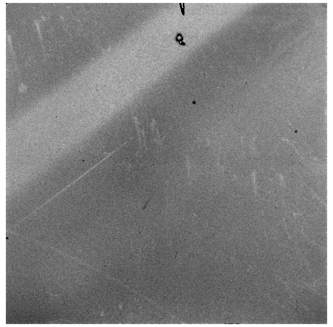
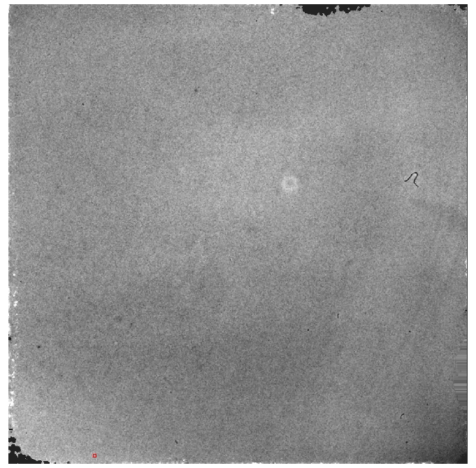
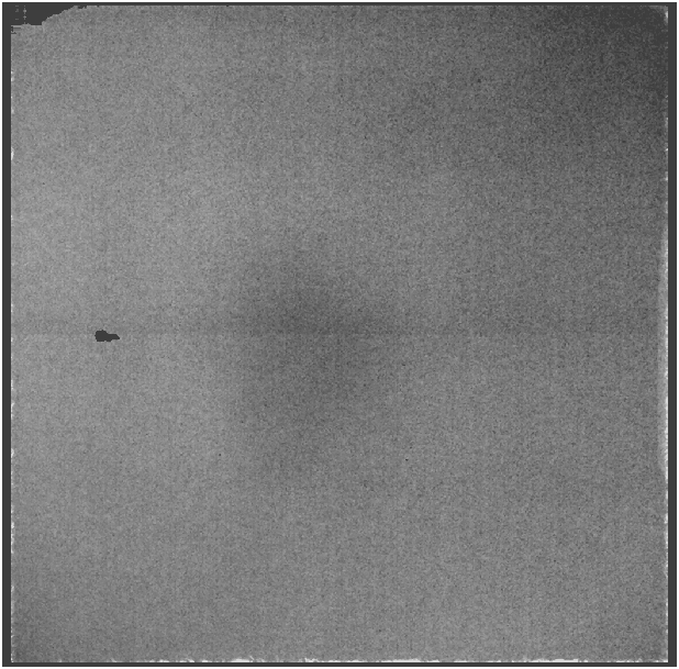
Reset images
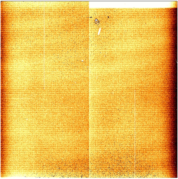
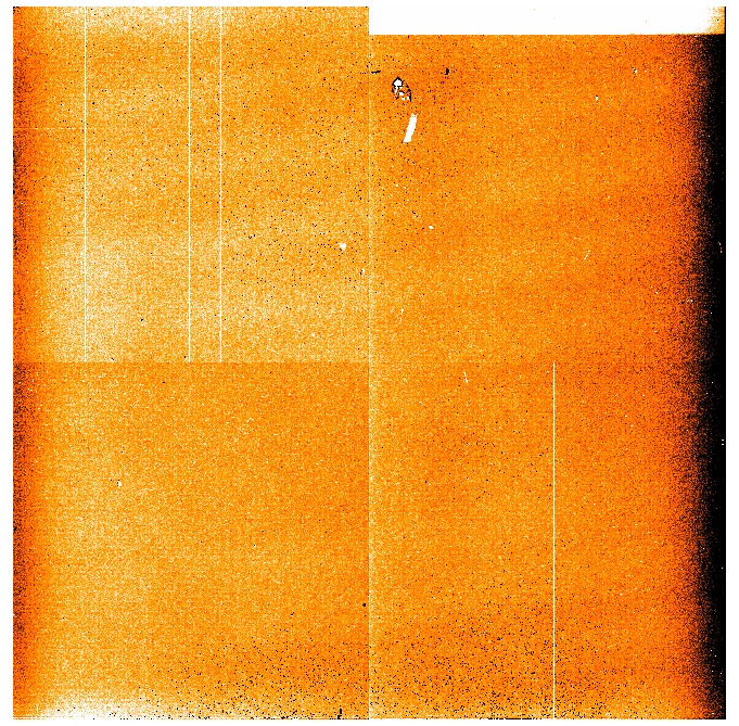
From left to right: 1) eng. array with new PCB, 2) eng. array with old PCB, 3)
the new science array with the new PCB.
Notes on reset images:
- The faint broad bands, tilted about 20 degrees, are the interference features that
are believed to be due to pick-up noise.
- We notice the presence of narrow horizontal stripes of alternatingly higher
and lower intensity. The stripes are stronger with the new PCB (peak-to-peak
amplitude 11%) than with the old PCB (peak to peak amplitude 7%).
- The stripes normally subtract out well, and there is no presence of such
stripes on the reset-subtracted images. For low-background cases, such as
darks, there are two exceptions, however: 1) where there is strong
interference pattern (due to pick-up noise?), and 2) along the first few
columns of each quadrant. Here the stripes don't cancel well.
- The stripes are relatively constant in time. The ratio of one reset image
with respect to the subsequent reset image makes the stripes go away and
the typical peak-to-peak noise amplitude is the same vertically as
horizontally: about 0.3 to 0.4 %.
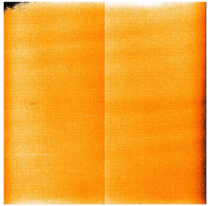
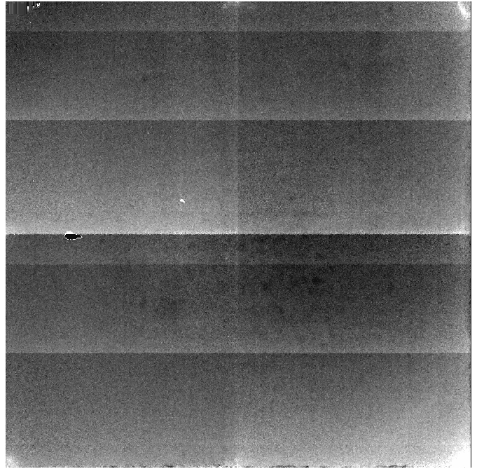
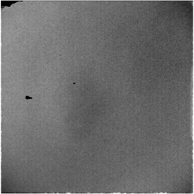
The reset level
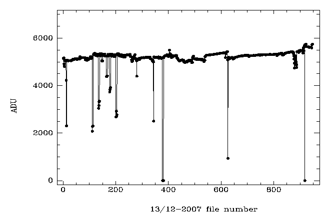
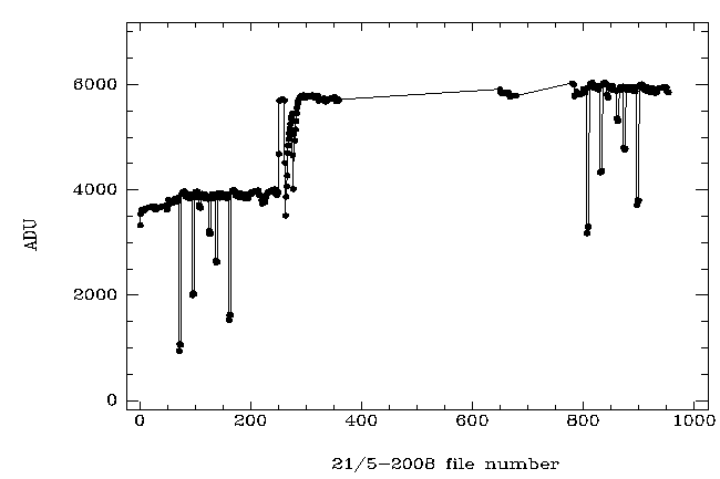
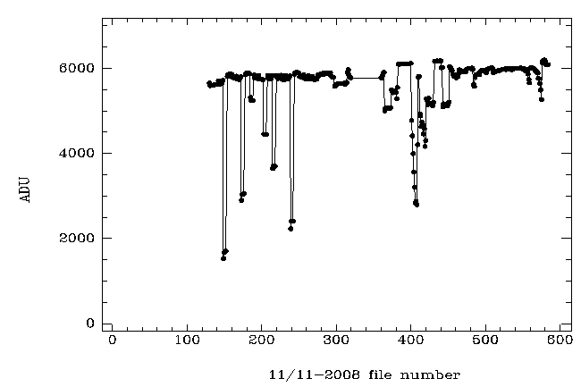
The reset level and its variation with time. From left to right: 1) 13/12-2007, 2) 21/5-2008,
and 3) 11/11-2008.
Notes on the reset level:
- The "dc offset" voltages were adjusted for each of the quadrants of the new science
array when commissioned 13/12-2007 to give around 5000 adu on the reset image. On the
first night after the vacuum improvements, 16/4-2008, the average level was found to
have dropped to around 3500. The "dc offset" voltages were increased by 0.02 V in each
quadrant on 21/5-2008 to reach a count level of around 6000 adu.
- The reset level is found to drop to very low counts on several occasions throughout
a night. If the level is very low it gives rise to "crap" images similar to the very
first images obtained after the array has been passive. A typical feature is that each
quadrant has a horizontal gradiant, and that there is a distinct jump between the right
and the left quadrants.
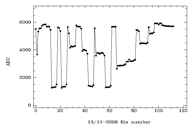
- A particularly bad situation was seen on 13/11-2008
during a daytime domeflat session during about 3 hours. The domeflats that have a very
low reset level are useless.
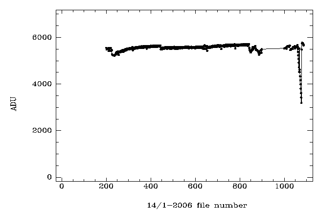
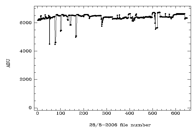
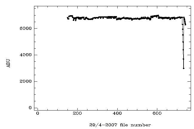
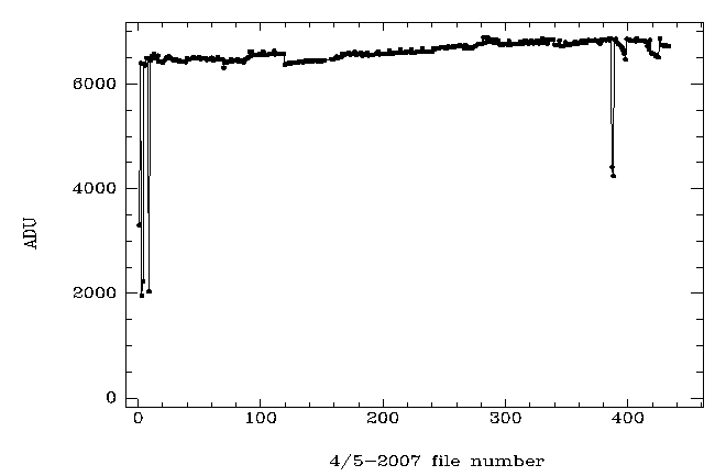
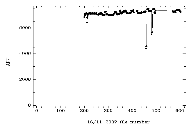
- Comparison with old PCB and old arrays shows that these instantaneous drops also did
occur earlier, but more seldomly or with smaller amplitude. See plots for
14/1-2006,
28/8-2006,
29/4-2007,
4/5-2007, and
16/11-2007.
Skyflats - comparison between the 3 arrays
From left to right: 1) masterflat for the eng. grade array (SWIR1), 2) master
flat for the first science array (SWIR2), 3) master flat for the new science
array (SWIR3). All are masterflats obtained in the same manner from differential
skyflats for WF-cam and the Ks filter.
Notes on sky flats:
- For the new science array (SWIR3) we note a pronounced structure outlining
quadrant borders, especially the horizontal border between lower and upper
quadrants. The above image is from December 2007. By April 2008 this effect is
even stronger.
- While the differential skyflat procedure (short exposures exp 5) used
to work well for the two previous arrays, it is not a useful strategy for the new
array. The jump across lower and upper quadrants has nothing to do with the
detector flat field. It is an effect related to the "reset anomaly" which is now
stronger with the new PCB. Because the "reset anomaly" has to do with the
detector's stabilization to a given intensity level, it does not subtract out well
on differential flats (bright - faint).
Skyflats - SWIR3
The average of all columns is plotted for SWIR3 WF-cam Ks band differential
twilight flats. Evolution in time from left to right: 1) 13/12-2007 2) 17/4-2008
and, 3) 11/11-2008. All are masterflats obtained in the same manner from differential
skyflats for WF-cam and the Ks filter.
Notes on SWIR3 sky flats:
- The plot shows all columns [1:1024] averaged. The dip around line 512 is the
effect mentioned above, the remnant of the "dc-gradient" visible as a horizontal
bar of lower brightness.
- On the commissioning night 13/12 2007 this effect was relatively modest (a dip
of about 2%) and did not catch our attention. The feature was discovered first on
the next NOTCam tech night in April 2008. The dip was then around 5%. Later is was
realized that the difference between bright and faint was exceptionally low on the
13/12 (due to a late dome opening caused by high humidity). On the 17/4, the
difference was typical with bright around 15000-20000 adu and faint around 2000 adu.
Domeflats
From left to right: 1) Differential (lamp ON-OFF) domeflat in J obtained
from 5 raw frames 4 5 images, 2) J domeflat created using only the
"lamp ON" images, and 3) the ratio between the two previous ones.
Notes on dome flats:
- The lamp ON images had 17000 adu and the lamp OFF images 2400 adu.
- Flat fields obtained with multiple reads using the ramp-sampling mode are better
than flat fields obtained with single reset-read-read exposures in the sense that
the structure of the 4 quadrants - which is related to the "reset-anomaly" and has
nothing to do with the flat field - slowly disappears the larger the value of
N in the command frames t N is.
- It is clear that differential flats, even when taken with multiple reads,
don't work well. The reason is that the OFF images are of a much lower intensity level
and therefore the ramp behaviour is different ("reset-anomaly") and does not subtract
out well. In fact, the subtraction adds structure to the flat. See the ratio image.
Conclusions
We have never tried the new array with the old PCB, but we know, from having used
the engineering grade array with both PCBs, that the new PCB increases the
"dc-gradient", the gradient across lines in each quadrant with highest amplitude
in the first few readout lines, a known effect with the Hawaii arrays referred to
as "the reset anomaly".
A consequence of this is that differential flats don't work well any longer for
NOTCam. Due to the "reset anomaly" the "dc-gradient" is different for different
intensity levels, and therefore the "bright minus faint" subtraction leaves
traces (most notably a horizontal bar of lower intensity across the centre of the
array).
It should be noted that the reset anomaly for the NICS/TNG instrument
is quite similar and makes it impossible for them to obtain accurate
differential flats.
Multiple reads gets rid of the "dc-gradient", but multiple reads require
of the order of 15-20 seconds exptime, not feasible on the twilight sky.
Domeflats are considered, but from earlier experience we know that they
are not optimal. This is still under study. Another option is to try to
get rid of the remnants of the "dc-gradient" in the differential flats
by collapsing a median column and subtract it.
Results of "dc-gradient" suppression in the mkflat.cl script
The option mentioned above, to get rid of the remnants of the "dc-gradient" in
the difference images by collapsing a median column and subtract it, has been
implemented as an option in the script mkflat.cl in the notcam.cl
quick-look reduction package. Every difference image in the stack is corrected
individually.

Differential twilight flat for WF camera and Ks band with "dc-gradient suppression"
(left) and without (right).
Comments to Amanda