


|
Mounting on the telescope
If you are going to dismount NOTCam from the telescope, then go to this link:
NOTCam shut-down and dismounting instructions.
- Power off the motor controller. (Also the detector controller, if this
one had been left on.) Disconnect power cables. Disconnect the orange
network cable from the plug in the dome wall. (Note that since June 2012
the optical fibers for NOTCam are always connected and go together with
the PTR hoses.)
Remove the black instrument
cover completely.
- Move NOTCam towards the telescope while lowering the PTR hoses
which have been lifted towards the dome ceiling. Detach the hoses
completely from the hook and lay them on the floor. Raise the hook
up again in the high position and fix it. Be careful when handling
the hoses! Do not lift the hoses over the instrument. Avoid sharp
bends that may produce Helium leaks, and make sure they have a maximum
of one loop when NOTCam is mounted!
- Take off the lid that covers the entrance window. Makes sure there is
no obvious dust particle on the entrance window. If so, blow carefully
dry air across it. Don't touch the window.
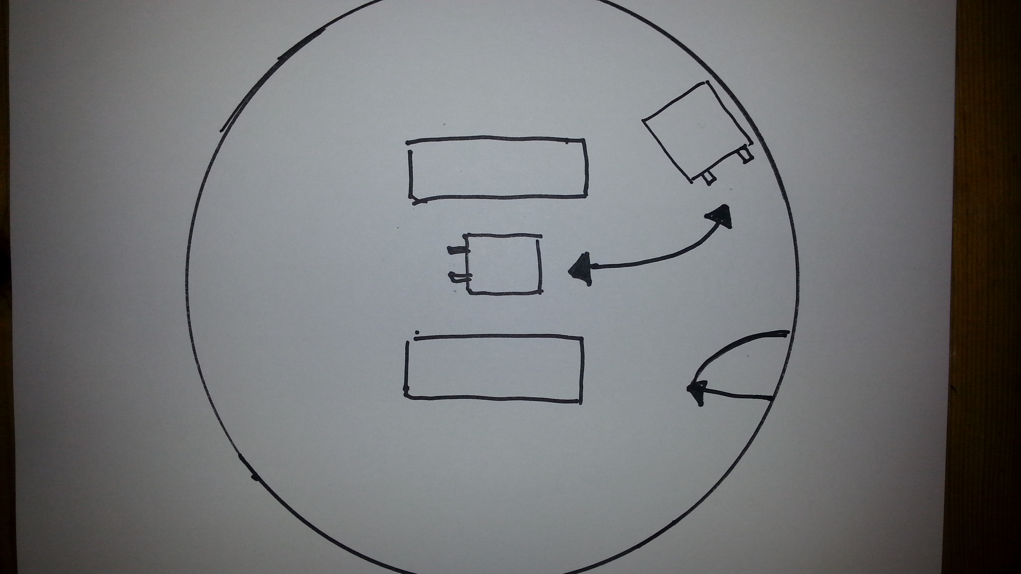
- NOTCam should be oriented with the tubes sticking out towards the
lower hatch direction, and the PTR hoses should have a maximum of one
loop on the floor. This is achieved by rotating the instrument about
100 degrees from parking orientation, i.e. the shortest way. Seen from
above this is clock-wise rotation. See schematic sketch
for which way to turn:
If NOTCam is also turned the correct way when dismounted, we will avoid
adding loops on the hoses.
- There are mounting marks on the instrument and on the adapter plate.
Use the handle to lift NOTCam on its trolley (but don't wind it too
rapidly as the chain may jump off its rail).
Mount the instrument flange to the adapter with the screws
found in a plastic bag on the NOTCam trolley. The differently coloured
screws are of different length and should go to the positions as marked
on the flange. The 2 red screws have to be fixed with a bolt at the upper
side of the adapter plate (use tool hanging behind entrance door). Before
taking the trolley away, fix and
tighten the 2 red and the all the yellow screws, i.e. on the StanCam side
and the side
towards the lower hatch. Also, put in the 4 grey screws you can reach
but only hand-tighten. Then remove the trolley, put in the remaining 2
grey screws and make sure all are tightened.
Note that currently (by Jan 2016) 2 holes in the adapter plate are
damaged at two yellow screw positions on the StanCam side!
- Mount the arm for the extra weights with 3 screws. The arm will stick
out towards the StanCam metal triangle. One of the 3 screws is 70mm
long, while the others are 60mm. Their position is marked on the arm,
never put the long one in under StanCam! Put on 43.75 kilos, i.e.
4 disks of 10 kg each, 1 of 2.5 kg and 1 of 1.25 kg.
- Check and connect cables:
- Connect the orange network cable to the 3Com network switch
on the adapter (any slot). Make sure the other end is connected at the
black small box called NPort 5210 next to the NOTCam motor controller.
-
Make sure the shutter cable between the motor controller
and the array controller has been connected, though this should never be
disconnected!
-
For shutter monitoring in
the control room, find among the cables coming through the hole in the
floor a grey cable marked NOTCam (Spare), wrap this once
around the thick grey NOTCam motor cables (to prevent the cable pulling
directly on the connector) and connect it to the virtually identical
connector from the motor controller. Tighten finger tight, don't use any
tools.
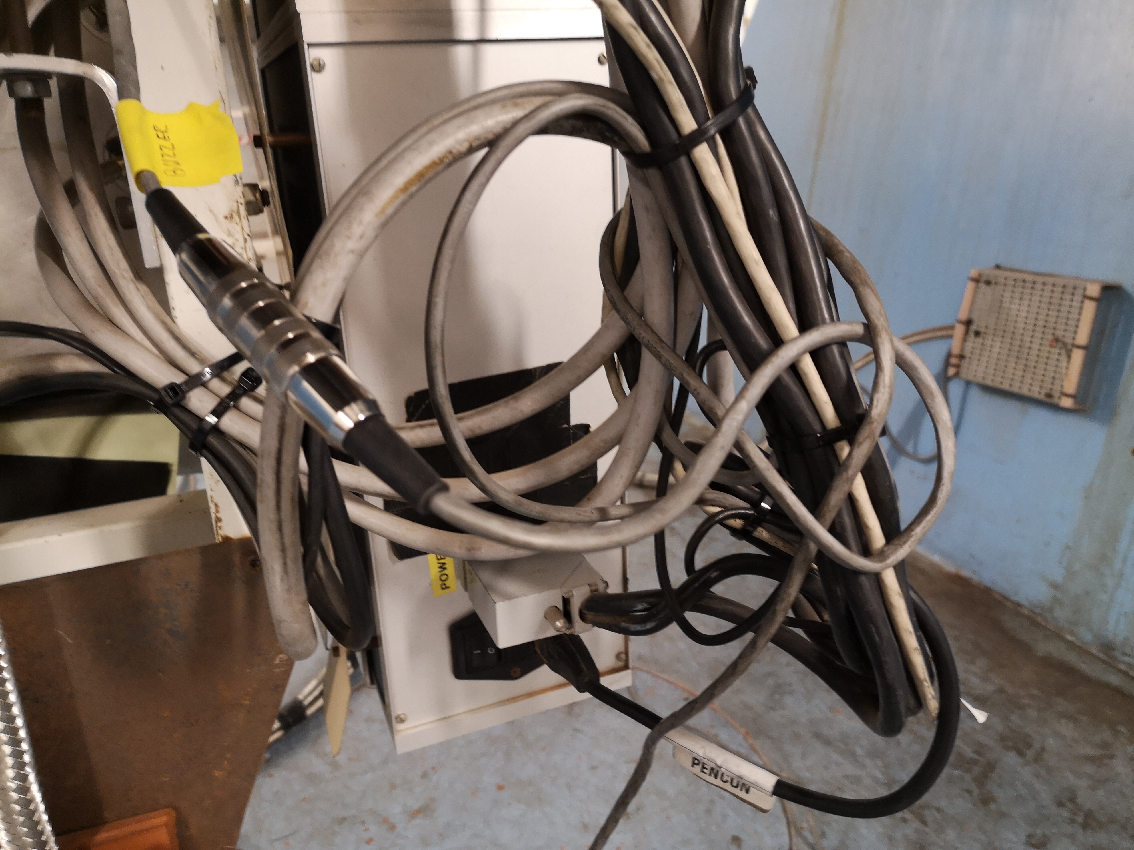
Click on image to enlarge
- Connect the black power cable to mains in the adapter. This
cable connects to the instrument via a rack of sockets. Make sure the
switch is on!
- Make sure that the fiber connected to the controller is not stressed!
- Make sure that the required LN2 for the night has been filled already
(it is not advisable to fill it just before mounting). Put the special
cork in the fill tube. NB! Only so far that just one black ring is
inside.
- Power on the motor and detector controller units.
- In the control room switch on the "NOTCam buzzer" on the wall behind the Lisa terminal.
This is the shutter monitoring alarm.
- See the
NOTCam Cookbook for how to start the software.
Make sure that both the camera and the motor controller respond.
Check that there are no timeout on any wheels.
Take an image, e.g. dark 0 to check that the array reads
out well. Note that the first few are always crap, so take 4-5 or more.
- Balance the telescope. Set the counter weights to position by typing on the TCS the command
count-w-hei .
-
You can check
how well the telscope is balanced by putting the telescope to
alt 60 (zenith angle 30) and opening the mirror covers
(o-m-c), and then look at TCS status page 3, where
the currents to the two altitude motors are displayed. These currents
(Altitude Motor 1 and 2) should have approximately equal absolute
values. Then type zenith to put the telescope back.
- The default
telescope focus is , and set with the command foc-pos .
This should be close to the real focus for the WF camera and any of
the K-band filters and is set automatically when running
tcs.setup-tel-notcam, which should be done when the telescope has power.
- Check web page: First night NOTCam goes on
telescope for the tests to be done in the afternoon and on the sky after
every mounting of NOTCam.
| |