![]()
![]()
![]()
![]()
NOTCam User's GuideContent of this page:
Check also these links:
Instrument OverviewNOTCam is a multi-mode instrument for use in the short-wave infrared (SWIR) region of the electromagnetic spectrum (0.8 - 2.5µm). It is based on the Rockwell Science Center "HAWAII" array with 1024×1024×18.5µm pixels in HgCdTe. NOTCam is capable of:
In the future we expect to upgrade NOTCam with Wollaston prisms for imaging polarimetry and spectro-polarimetry. On entering the front window of the dewar, light passes through the following components before impinging on the detector ( engineering grade array (SWIR1) , first science grade array (SWIR2) , new science grade array (SWIR3) ):
Since NOTCam is kept cold for long periods at a time, we do not change filters, slits, grisms etc. more often than absolutely necessary (see the current setup). The original optical design is described here (pdf). This entire assembly is mounted on an optical bench which is in thermal contact with an LN2 tank. Additional cooling is provided by a pulse-tube refrigerator (PTR) from Iwatani. The optical bench is covered with a radiation shield and this and the LN2 tank are surrounded by a superinsulating blanket. The final enclosure is the dewar skin which maintains a high-quality vacuum surrounding the instrument. More about Mechanics and Cryogenics. The SWIR detectorThe NOTCam detector is a HgCdTe Rockwell/Teledyne "Hawaii" array with 1024 x 1024 x 18.5 microns pixels.
Together with the upgrade from SWIR1 to SWIR2 in December 2007, there was also an upgrade of the NOTCam Array Electronics. The first science array, SWIR2, failed after 6 months and was replaced by a new science array, SWIR3, which has been used since December 2007. Each detector has (had) its particular characterics, described in the above links to the detector verification pages. An upgrade of the clock boards in January 2010 improved the performance of the currently installed SWIR3 detector in removing the shift-register glow and lowering the read noise. The behaviour of the detector is continuously monitored in our Detector Quality Control.
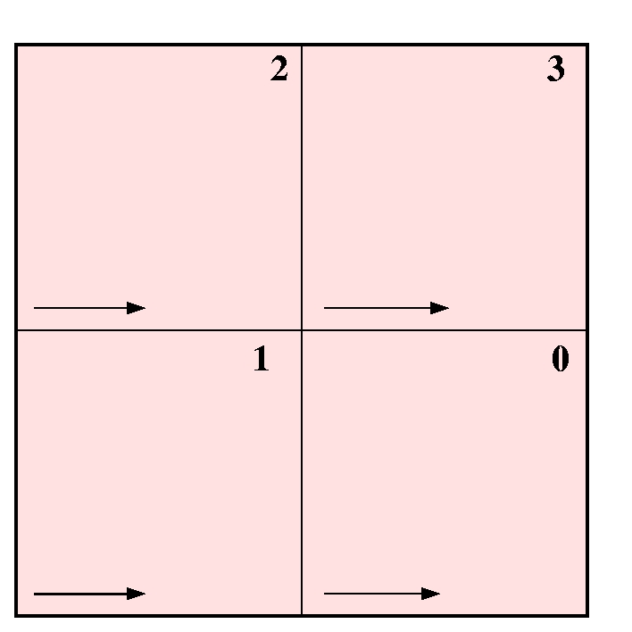
Schematic drawing of the detector with the four quadrants marked in the numbering system used by Copenhagen University Observatory (CUO) for NOTCam. (Note that Rockwell/Teledyne numbers from 1 to 4, but in the same order.) The arrows show the direction of the fast readout and the corners in which it starts. All four quadrants are read out simultaneously. Left: Valid from 2001-2005. The lower left corner of quadrant #1 is the location of pixel (x=1,y=1). Right: Valid since Jan 2006. The lower left corner of quadrant #0 is the location of pixel (x=1,y=1). LN2 spillingThe liquid nitrogen vent tube of NOTCam will spill LN2 when moving the telescope in certain directions. Observations made at an airmass larger than 2 and at given rotator positions (especially between -20 and -80) may cause substantial spilling. A default telescope rotator angle for NOTCam (field-r -90) was chosen to minimize this spilling.Since January 2003 NOTCam is running on the PTR also while mounted on the telescope, and the problem of spilling LN2 is no longer that critical in terms of temperature stability of the detector. For typical nights the detector temperature is as stable as +- 0.1 degree. Tracking a target at very low airmass for a considerable time causes some spilling and the detector temperature deviation will be larger, but in general this is not a problem. NOTCam is re-filled with LN2 in the mornings in order to make sure that any deviations due to spilling are corrected before the next night. See NOTCam filling (internal page with limited access). In 2009 the vent tube got an extension fitted such that LN2 will spill from below the instrument to avoid dripping on sensitive parts. Shutter monitoring - "the buzzer"The first half year of NOTCam commissioning we had problems with a malfunctioning shutter. Since Dec-2001 we have seen problems with it only a couple of times. Since there is no closed-loop feedback on shutter position a device was designed to warn the observer if the shutter is not correctly positioned. This warning will be given as a loud "buzzing". If this happens, you first have to check the behaviour of the LED lights on the device to check if something really is wrong. The device is found on the wall in front of you, and it has a reset switch for turning off the "buzzing". The correct behaviour is that the right LED is lit during every exposure and the left LED is lit during every second exposure. If the left light is merely blinking (not stable during the time of an exposure), this is the first indication that the shutter is out-of-sync. If this happens, try first to initialize the shutter by clicking on the Initialize menu in the UIF, and then on the Init Shutter button. If this does not help, then the array controller may need resetting. Contact staff for this. It can also happen that the shutter hangs open or closed. If the lights behave correctly, however, and the "buzzer" still went off with a laudible alarm, just turn off the alarm by pressing the reset button on the "buzzer", and continue to observe, as it probably just picked up noise somewhere. Please, note that you can not turn off the alarm during an integration, only after. Sorry!Field orientationThe default field rotator orientation is field-r -90. Of course, you can use any field orientation you want, which you will for instance if you do spectroscopy on the parallactic angle. Originally, field-r -90 was selected as the default since it causes less spilling of LN2.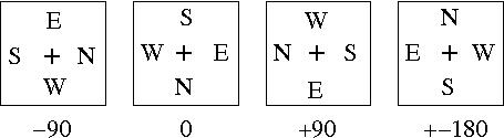
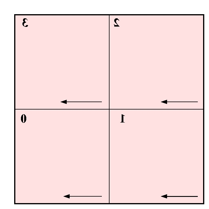
NOTCam orientation on the sky for different field-rotation values. If you wish to rotate the image on the DS9 display to have North Up and East Left, you can click on Zoom and then tick the Align button, or alternatively, using the command line, you can toggle alignment on/off with the sticky command notcam.wsc-align yes/no.
field-r -90 gives South left and East up in the images displayed
both on the BIAS DS9 (left) and the post-processing DS9 (right). Since
Jan-2006 when changing data format to Multi-Extension-Fits
(MEF) the stored images are flipped in X with respect to the images
in the real time buffer (left DS9). Note that the image shown on the BIAS
DS9 (left) is flipped in the display only in order to avoid confusion! (Its
X values are not flipped and X increases from right to left! NB! You
should not use the BIAS DS9 to measure positions!) For example, for field-r -90, the telescope(!) moves 10 arc seconds:
If you are using another field orientation and want to know exactly in which cardinal direction you are moving the telescope, you can do the following test. Set previous image for sky subtraction on the DS9 with setskysub 1 and take an exposure. Move the telescope 10'' in any direction using teloffset, and take another exposure. On the DS9 you will see the current position and the previous position (negative) and by clicking the Zoom and the Align buttons on the DS9 it should be evident in which direction the star has moved, meaning the telescope has moved in the opposite direction. If you are preparing your observations and you want another field orientation it is advised to use our Pointing Script Generator where you can indicate your sky position angle in degrees and the corresponding telescope field-rotation is calculated.
Flat fields
We recommend differential twilight sky flats rather than dome
(lamp ON-OFF) flats.
Dome flats are not perfectly flat at the NOT. Thus, if weather allows in
the evening, point to a selected
blank field
in the east about 10-15 min before sunset and then open the dome (i.e.
select a field with RA a couple of hours more than current ST to make sure
you avoid pointing towards the sun in the west). For the
morning twilight point to the west (RA of blank field being 2-3 hours less
than the current ST) about 30-40 min before sunrise and remember to close
the sideports first. Also, close the dome completely before parking
the building in the morning if you continue until after sunrise!
Use the NOTCam Sequencer observing script:
The New Science Array (SWIR3) flatfield (WF camera, Ks-filter) is flat to 1% in 20x20 pixel areas and flat to 3% across the FOV, and looks about the same in all filters. Flat field corrected science frames are typically flat to 0.1%. See SWIR3 flat field. The observing script notcam.skyflat t should take about 3 minutes to perform. This short duration ensures a sufficient sky gradient for each filter within 10-15 minutes elapse between the first and second measurement, which is acceptable for subtracting the thermal contribution, while it allows time for 2 cycles of 3-5 broad band filters. The script notcam.skyflat automatically saves the raw NOTCam flats to the /data/service/calib/ directory. If you could not get skyflats for all your filters, the second best option is to use differential domeflats. Because of the structure on the inside of the hatch, we recommend setting the telescope to alt 45 or so, where the inside of the dome is a bit "flatter". Differential dome flats can be taken with the NOTCam QC lamp (adjustable from the control room) ON and OFF in each filter. NB! The integration time must be the same for the ON and OFF frames. For the HR camera, it is useful to use mexp 20 10 for all filters, lamps turned on full for K-band and a bit down for J and H. For the WF camera mexp 10 10 is useful for the same adjustment of the lamps.
There is also a NOTCam skyflat archive with master
flats for the most commonly used filters taken at different dates.
FocusingWe recommend to focus every evening using the WF-camera and the Ks band and apply the focus offsets for the other filters as found in the table below. This is done automatically when using the setup scripts notcam.setup-ima and notcam.setup-spec, where the corresponding focus-delta offset is applied, taking as a reference the focus found for WF camera imaging in the Ks band, which is defined as the default NOTCam focus. The focus offset is wavelength dependent so for the narrow-band filters we use the focus offset for the closest broad band filter.
*) This is the default NOTCam telescope foc-pos value, but it may vary by up to around 100 units, and this is the focus value you should determine every night by focusing the telescope in the Ks filter. Usually, the accuracy of the focus correction is around 10-15 steps, but note that with a seeing of FWHM=0.3'', telescope focus steps as small as 5 units make a difference. Remember to take out the focus pyramid when finished. If you are doing NOTCam spectroscopy the internal focus setting differs between camera, filter, and slit used, and the easiest way to set both the internal camera focus, as well as the telescope focus offset, is to use the setup script notcam.setup-spec. Also for spectroscopy, the telescope foc-pos value should be set to the default or the one found for the night by doing focusing for the WF camera and the Ks band.
The sky background
This corresponds to roughly J = 15.9, H = 13.9, and Ks = 13.2 magnitudes per square arc second. Individual exposure times - Number of co-averagesThe absolute minimum exposure time handled reliably by the cold shutter is 0.6 sec. However, the shutter has a tiny delay. Without correcting for this one the accuracy of a 2 sec integration is only 3%. For exptimes larger than 3 sec the accuracy is 1%. The sky background is high in the near-IR, and a sufficient amount of counts to reach BLIP is usually obtained within a few seconds for broad band imaging. For narrow-band imaging, on the other hand, the time to reach BLIP should be carefully considered.
For more information on sensitivity and zeropoints with recent updates check page: NOTCam sensitivity .
The background is highly variable, and strongly temperature dependent for the K band. The airglow lines are most prominent in the H band and their brightness may change by up to 50% during a night, while the typical amplitude and period are 10% and 5-15 minutes, respectively. For a typical cold winter night with an ambient temperature of 3 deg Celsius, the background will saturate in individual exposure times of 1000s, 235s, and 160s for J, H, and K, respectively. These saturation times will be shorter for warm summer nights. In addition, you will typically want to have the background within the linear range of the detector, limiting the exposure times to 360s, 80s, and 70s in J, H, and Ks for cold winter nights. In warmer nights, when the water vapor content is higher, or in the case of thin clouds, you may have to limit the exposure times much more, for instance 30s in H and Ks is sometimes found to be the limit. The detector is non-linear in response, and staying below ~20000-25000 adu only means staying inside the range where the non-linearity is < 1%. It is possible to correct for the non-linearity, pixel by pixel, and the non-linearity correction coefficients can be downloaded form the NOTCam Calibrations page. The memory (or charge persistency) effect is less than 1% and cleared on the first read for non-saturation levels. For saturated pixels, however, there is a positive memory which persists for many reads, although at a relatively moderate level of less than 0.03% in the 6th readout. It is recommended not to saturate the array, if possible. If impossible to avoid, and if the saturated pixels are close to your target, then it is recommended to clean the array with the command clear which resets and reads the array once without showing or storing the image and which takes 3.5 seconds to perform. Depending on the expected severity of the memory, the clear command may be applied once or several times. There is also a script called notcam.clean3 which makes 3 clear commands and then a dark 0 to show you the result. It is generally stated that as long as one is in the BLIP regime, it is better to take many co-averages to increase signal-to-noise, rather than increasing the individual integration time. This is not entirely practical with NOTCam. The reason is the large overhead owing to a relatively long readout time (3.6 sec per read, 7.2 sec in total per image) limited by the current detector controller. We expect a readout time of < 1 sec with the new controller. Note that the ramp-sampling mode gives a large dynamical range, since you save a number of integration times in the fits file (see below). If you saturate (or enter non-linear mode) for very bright targets while you want to go deep for faint targets in the same field, you can select to use one of the first reads in the cube for the bright sources. Note, however, that saturation will produce memory effects in several consequtive images, and you may want to add in the clean array command clear once or more between each exposure to minimize this effect.
Dithering strategyMake sure that you repoint the telescope to the start position at the end of every observing script, or to any position you want, such that you keep track of where you are upon possible repetitions of the macro. Between every repetition of a dither pattern you may do a manual offset to some roughly random direction by just typing notcam.teloffset x y in the Sequencer window. In this way the same pattern is not repeated on the same pixels. You can use our available template scripts such as for instance:
In general, autoguiding is always recommended. Note that since 2007 there is no additional overhead in dithering sequence owing to autoguiding. The Script Generator is a useful tool which also gives you an idea about the overheads involved. Point sourcesFor point sources the most efficient method is to obtain an image from a set of slightly dithered images. One or more images are obtained per sky position before moving the telescope. The total time per sky position should be at most a couple of minutes. It is recommended to use a step size of at least 10 times the FWHM of your objects. This permits using the target images themselves to evaluate a local sky frame to be subtracted (median filtering). Therefore this method is more time-efficient than taking off-field sky images, which is needed for extended objects. A frequently used mode is the 3x3 dither with 10'' step sizes. For standard stars and bright sources the 5-point (dice) mode is usually sufficient.
If the target is not contained fully within one field, make a mosaic. The mosaic can be made as a raster scan which can be repeated again and again until you reach the desired sensitivity. Note that you should dither the telescope a small amount between each repetition of a raster scan to be able to remove the bad pixels and bad features from your sources. For each scan, depending on its size, all or groups of the target frames can be used to create a local sky frame (provided they don't contain extended emission). If there is a small amount of extended emission in a small fraction of the N mosaic frames, these can simply be excluded when making the sky frame. Note that depending on the dither steps you plan to make, the corresponding guide star area must be selected when doing target acquisition. This is explained in the Autoguiding section in the Step-by-step observing guide. Extended sources or crowded regionsIf the target is extended or very crowded (e.g. a strongly centrally condensed globular cluster), then small step dithering is not sufficient. In this case, so-called "beam-switch" observations are required. This means observing one or several sky fields off the target itself. The off-field(s) must be sufficiently away from the target that no extended emission is included. Observations must be alternating between target and sky staying at most a couple of minutes in each position, and each sky and target position must dithered (step size at least 10 times FWHM) to filter away stars (and bad pixels). Note that the Script Generator is not yet capable of producing beam-switch scripts, but there is an available template script called notcam.beamswitch that can be used.
NOTCam data acquisitionWith NOTCam there are three different commands to start an exposure. Users familiar with BIAS (Brorfelde Image Acquisition System) will recognize two of these from the BIAS versions in use with CCDs (exp, mexp). For IR arrays the data acquisition is different, however. In contrast to CCDs, where the same Si array is used to collect the photons and to read out the photo electrons, IR arrays are hybrid devices with one array for the detection of photons (HgCdTe layered on a a sapphire substrate) and another for reading the photoelectrons (the multiplexer constructed using conventional Si based CMOS technology). The two are manufactured separately, then aligned and connected pixel by pixel with small bumps of indium. Each individual photodiode (the IR sensitive HgCdTe) and its corresponding electronics on the multiplexer (together comprising one pixel) possess a given electrical capacitance C. The voltage V across this capacitor is set to a given value when the pixel is reset. The reset switch on each single multiplexer circuit is closed at the beginning of an integration, thus charging the capacitance. During an exposure, the reset switch is opened and incoming photons release electrons which discharge the capacitor ( dV = dQ/C). At any time during the integration (before the next reset) the multiplexer can read the detector, i.e. measure the voltage across each capacitance, without changing its value. This is called non-destructive readout. The multiplexer is divided into four independent quadrants, each with its own clock and bias lines and its own output amplifier. Each quadrant is read out simultaneously. There are many different readout modes for multiplexed arrays. With NOTCam we offer two modes:
We strongly recommend to save all individual images.
About darksPlease, note that the dark current measured with NOTCam is non-linear, variable and higher than the specifications (which state less than 0.1 e/s/pix). See NOTCam Darks - internal summary for more details about the darks, and see NOTCam Calibrations for examples of dark images. For imaging in the background limited case, we thus do not recommended to correct for the dark level by taking separate dark images that are aquired at a different time. By using differential flats and sky subtraction, as usual in infrared image processing, the dark level will automatically be subtracted out. For spectroscopy mode, however, we recommend to take a set of darks with the same readout mode and integration time as your observations, although spectroscopy is also done in differential mode (subtracting a dithered image). But since the number of dithers is less, for practical reasons, darks are useful to estimate a hot pixel mask. The number of hot pixels increases with the integration time. For this purpose, the calibration script notcam.notcam-calibs at the end of the night is useful. NB! Please, note that the linear regression analysis image for darks taken with the dframe t N command is not reliable, since the dark current is not linear (but this is not important for finding hot pixels). What are the overheads?
New! Since November 2011, the exp mode is speeded up by letting the telescope move as soon as the shutter is closed, i.e. while reading out, subtracting, showing on real-time display and storing the data file (marked in red above). The measured total time spent is lowered as follows: Tnow/Tbefore = 0.76 for exp 3 and 0.82 for exp 10. This does not apply for staring mode observations.
These are measured overheads for NOTCam (Feb 2011) :
Note 1) Time to add to the exptime when using exp/dark . This includes the time it takes to read the array twice (2 x 3.6 s) plus the time to store the 4 MB file (2 s) plus any possible delays in the acquisition system. From November 2011, when these exposure commands are followed by a telescope dither, observing is speeded up by letting the telescope move while doing the 2nd readout, saving about 5-6 seconds of total overhead. This does not apply to staring mode observations. (During 2008-2010 the overhead was ~ 13 s, while during April and May 2007 it was as high as 18-20 s.) Note 2) This includes the time needed to read the array once (3.6 s, since the other reads are interlaced with integration), to store the large file (up to 7s for 32 MB), and any possible delays in the acquisition system including the linear regression analysis (up to ~1.4 s). Note that when the time between non-destructive reads (i.e. the t in "frame t N") is < 5 s, there are internal delays in the PC-board (see NOTCam BIAS for details). This may increase the overhead with 2 s per frame command. The following note was valid from 2007-2010: The total time needed per command occasionally becomes much larger if the program experiences hick-ups (up to 150s), a problem present from Apr-2007 to Oct-2010, for the frame command. Both the average overhead values and the frequency of hick-ups were variable with time. This additional readout overhead was quite impossible to predict. Note 3) All wheels can be moved simultaneously! The wheels move in one direction only. The two filter wheels, the grism wheel, and the stop wheel all take ~ 30 s to make one full turn. NB! The time to do telescope dithers has increased slightly since Nov-2007. The reason is the introduction of an extra wait such that the telescope has come to a complete rest before the next integration starts. Tested for 240" teloffsets and short (2 s) integrations using the HR-camera in 0.3" seeing. The earlier appearance of elongated stars in such extreme conditions has now been remedied. Note that the exact time needed to make a given dither depends on how much of the movement is in azimuth. In the above table are given the value ranges measured on a number of tests.
The frame command is normally more time efficient than the mexp command. This is due to the long readout time, and the use of a shutter to determine the exposure time. If you need individual exposure times shorter than 3.6 seconds, you must use the exp or mexp command. Nominal overheads are calculated by the Observing Script Generator.
Observing scripts
Warning: When using the Script Generator to create scripts, please, note that you must check yourself whether you have chosen an allowed exposure mode. Also, we warn that using cut and paste from the output on the screen in for instance a windows browser will add strange characters to the commands and give serious problems in the execution of the scripts. Check your scripts well!
It is very useful to add one of the two following lines at the end of the
scripts: playphone astrowakeupThese are audible and visible alarms to the observer that the script has finished.
CalibrationsStandard starsSee also: Northern JHK Standard Stars for array detectors by Hunt et al. (1998, AJ 115, 2594) (or see local ps files: paper and erratum ). Contains 86 stars in 40 fields, many of which are faint enough to observe with the frame command. Another advantage is that many of the fields have multiple standards. We recommend using the same readout mode for the standard as for the target.
The data formatData taken from Jan-2006:Multi Extension Fits (MEF) format is now used. Major upgrade of the FITS header keywords. For more information check the page New data formats and FITS headers.Note that the images are now flipped in the X-axis with respect to images taken before Jan-2006. Data taken before Jan-2006:The data was stored in fits cubes. Check this example of an old NOTCam FITS header which contains explanations to some of the specific NOTCam header keywords.
Renaming of FITS header keywords Oct 2012:Several instrument related fits header keywords changed name on October the 1st 2012. This includes the old keywords APERTUR, FILT1, FILT1ID, FILT1POS, FILT2, FILT2ID, FILT2POS, STOP, GRISM, LENS, CAMERA that are now called NCAPRNM, NCFLTNM1, NCFLTID1, NCFLTPO1, NCFLTNM2, NCFLTID2, NCFLTPO2, NCSTPNM, NCGRNM, NCCAMNM, NCFOCUS. For details see the comparison between an image with old header and new header.
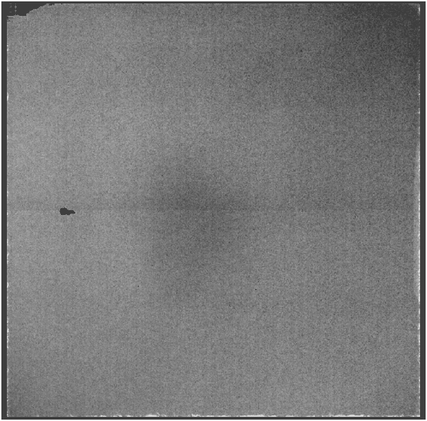
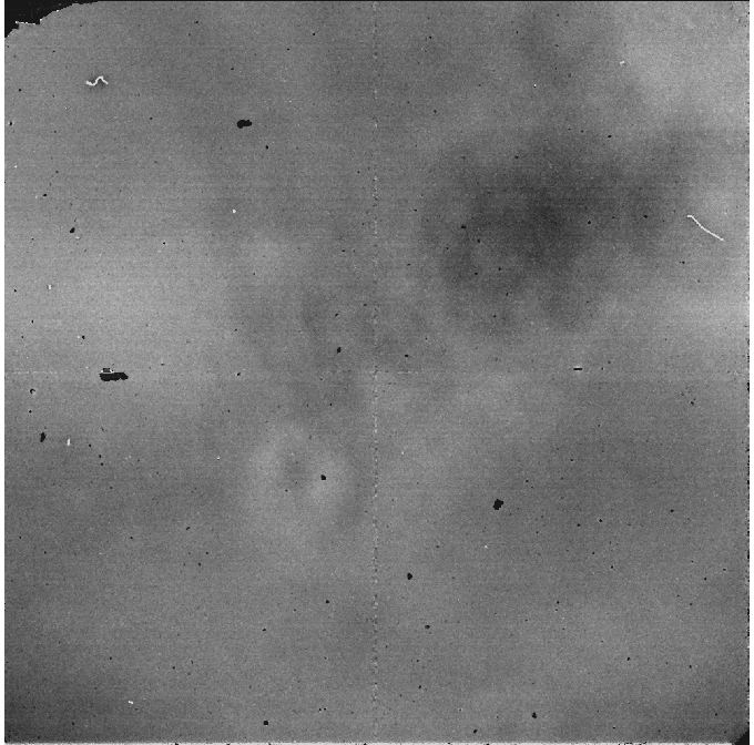
Encountered problemsCondensation on the entrance windowIf during observations you get an image which looks like the following:
Condensation on the entrance window. then there is water condensed on the entrance window of NOTCam. This can happen if the humidity inside the dome is very high over a long time, or if there is some problem with the vacuum in the cryostat. Observations can not be continued. Call staff. NOTCam must be dismounted on its trolley and lowered down to remove the condensation.
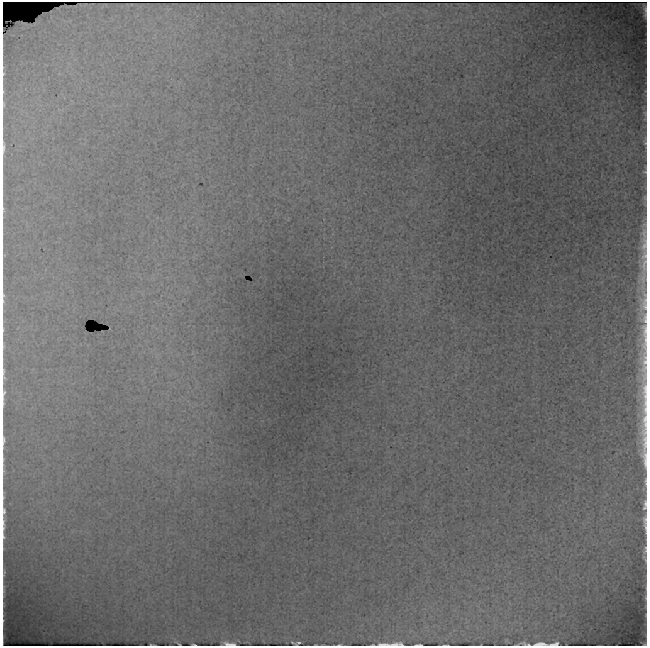
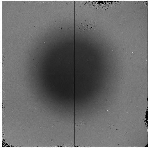
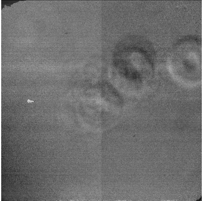
The appearance of a dust speckThe image below is an example of a large, out-of-focus particle. The image is a ratio image of a WF-camera J-band masterflat from the 5/3-07 to that of 4/3-07. The particle is just barely visible in raw images unless it moves between the two images used to make a difference image. In the below example the light attenuation effect is 3% in the worst part. If the particle is moving around, its effect can not be flatfielded out, but with a number of dithered images, the effect should diminish. If you see such a feature in your images, please, submit a Fault Report about it. If the placement of the feature in the FOV is very disturbing, it might be a good idea to move the telescope down and up, perhaps turn the rotator with the telescope down, to try to get rid of it, although this may not help.
 Large dust speck. This is the ratio image of a J-band masterflat from the 5/3-07 to that of 4/3-07. The largest difference inside the dust speck is on a 3% level. The rest of the image has a value of 1 within 0.1 to 1 %, and a standard deviation around the mean of 0.004. If the particle is on the entrance window, then NOTCam must be dismounted and the entrance window inspected and cleaned. Before doing this, change to the other camera and make a ratio image of domeflats with the two cameras. This should reveal whether the particle is on the camera lens inside NOTCam. In the example here the ratio image between a HR-camera J-band domeflat and WF-camera J-band domeflat shows that the particle is located on the WF-camera lens. See image below. Note that the feature has moved from lower right to lower left quadrant. Since the particle is inside NOTCam, we can not do much until the instrument is warmed-up and opened.
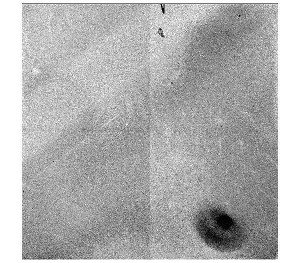
 Ratio J-band domeflat between HR-camera and WF-camera. In addition to the large feature (now moved to the lower left quadrant) there are also 3 smaller and rounder features at about 1% level or so. The greyscale is negative so the dark features means they are present on the WF camera image and not on the HR-camera one.
Pick-up noiseIf your images have a disturbing pattern of almost horizontal stripes this could be the problem of pick-up noise recurring. The problem was found to be caused by the power supply in the electronics of the array controller.
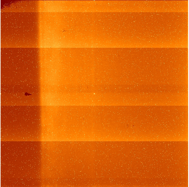
The 9th of June 2009 eventOn the 9th of June 2009 there was a sudden increase in the number of bad pixels. This is demonstrated by the two WF-camera J-band master flats below, where the first one is from the 8th and the second from the 9th of June. The cause of this is not well understood, but it is believed to be related to a shaking of the telescope caused by the failure of an altitude tacho during powering on. The largest of the new bad-pixel areas have a very low response, only about 40% of the surroundings. The many more lower response pixels are probably caused by tiny dust particles deposited on the array after the violent shaking of the telescope.
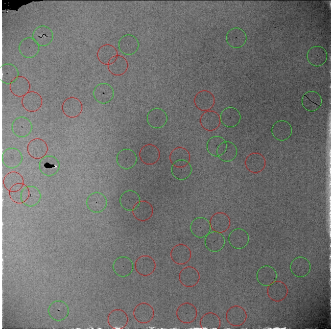
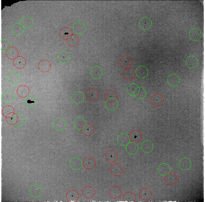
New bad pixels on SWIR3. Green circles mark already existing bad pixels, while the red rings mark the new bad pixel areas appearing overnight. Note that two hair-like features seem to have disappeared on the second image. Also the flat-field structure changed at the same time. See below the ratio of the flat in J-band from the 8th to that of the 9th (left). The response is about 4% lower in the dark big area in the upper right quadrant. Probably this is due to dust having fallen down on the entrance window. The entrance window was cleaned on the the 10th daytime, and the ratio flat between the 10th and the 9th is shown to the right. The remaining structure is due to (moving) dust on the WF camera lens inside the cryostat. The amplitude in this case is at most 1.5%. The gradient in the lower left corner is 1%.
Ratio flats for WF-camera and J-band, between 8th and 9th (left) and between 9th and 10th (right). To the left is shown the dust on the entrance window which in the darkest part has about 4% lower illumination than the surroundings. To the right is the remaining structure after having cleaned the entrance window, and this is due to dust specks on the WF camera lens that have moved slightly. The peak to peak amplitude here is around 1%.
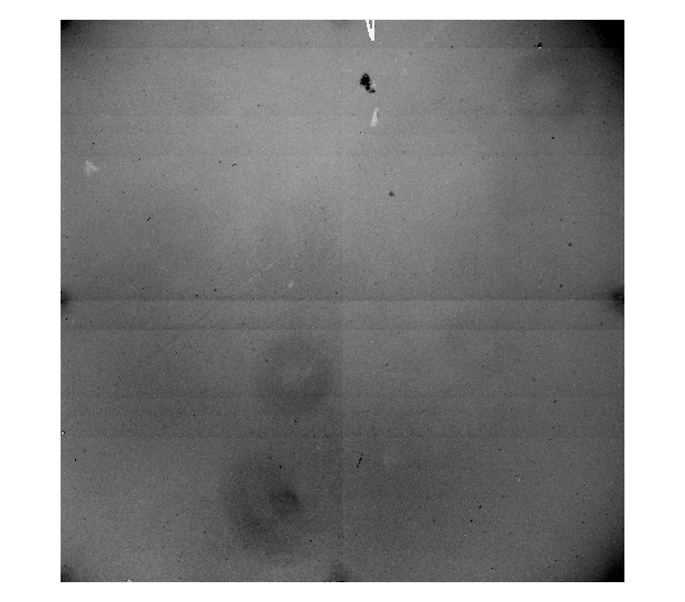
Strange darksLong darks (i.e. dframe 60 6) taken with the internal focus setting below 1000 units, typically used with the HR-camera, have more counts and a distinct structure compared to equally long darks taken with the internal focus setting is at higher values, such as 5650 which is typically used with the WF-camera. The median pixel value in the area [260:310,650:700] is 360 adu in the left image and 16 adu in the right one.The problem is currently under investigation.
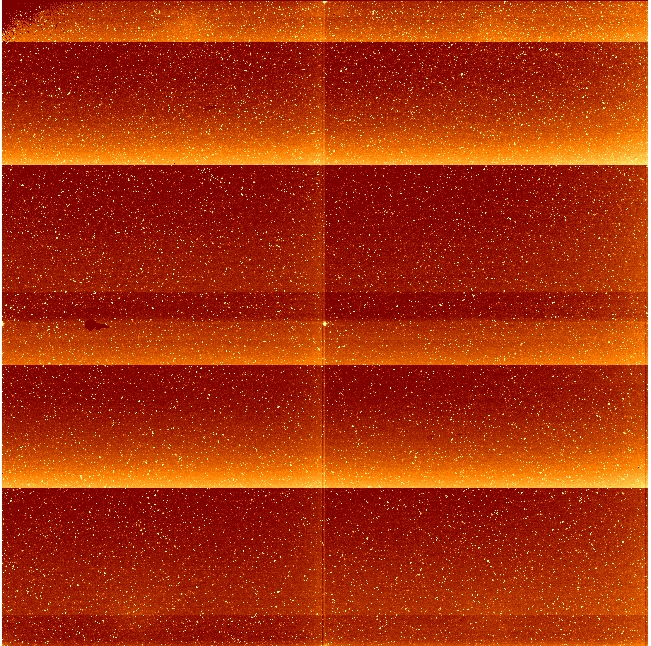
360 second long darks using "dframe 60 6" taken with the internal focus value at 20 (left) and internal focus value at 5650 (right). The left corresponds to the detector plate being at the furthest distance from the camera wheel. This is the focus value used for HR-camera imaging.
NOTCam Quicklook reduction package
NOTCam package in IRAFA small NOTCam package of iraf scripts (notcam.cl) is available on the computer florence in the control room. NB! This is not a pipe-line.The purpose of these scripts is to take a quick, but reasonably fair look at the data obtained.
Upgraded to version 2.5 in October 2012.
NB! Note that the scripts reduce and reduce_bs does the image registration satisfactorily only on data obtained after 15-Nov-2007, since until then the RA/DEC fits header keywords were not accurate. This was because of a bug in the output coordinates from the TCS, although the actual TCS coordinates were accurate. Note that for quick-look you don't have to make badpixel and masterflat images, but may download these directly from our archive flat fields and bad pixel masks. You may also wish to download the correction files for non-linearity and optical WF-camera distortion from our archive non-linearity correction models and distortion models. Get started as follows:
Before starting the reductions you should be aware of the optical distortion of the WF camera (see below) and see the note about NOTCam darks. Note on the optical distortion of the WF cameraThe optical distortion of the WF camera in NOTCam is significant, especially in the corners.From version 2.4 of notcam.cl you can select to correct the images for this distortion in the scripts reduce and reduce_bs. These will need the input file "notcam.db" which contains distortion models for the three bands J, H and Ks for the WF-camera. These models are based on high-quality (fwhm = 0.5'') data from 2009 of a stellar-rich field (~ 300 2MASS sources). See NOTCam Calibrations - Distortion Correction for more details. An earlier NOTCam distortion model was provided in 2005 by Magnus Gålfalk based on his observations of B335 made with FWHM=0.5''. The model is calculated from more than 100 stars in the field using the 2MASS catalogue as positional reference. It is available for download at the web page http://www.astro.su.se/~magnusg/NOTCam_dist/. Please, note that images obtained after Jan-2006 are flipped in X and this old model must be correspondingly adjusted.
The HR camera has an excellent optical quality all over. See the NGC4147 image in the H-band obtained with fwhm = 0.44'' and ellipticity typically 0.02 to 0.05 all over the FOV. The pixel scale of the HR camera is 0.078''/pix. Note on NOTCam darksPlease, note that the darks are not fully understood. We do not recommend using darks in the data reductions of broad band imaging. The dark current is automatically subtracted out together with the sky. The dark is also automatically subtracted out when you use differential flats (twilight or dome). For long integrations in spectroscopic mode, we still recommend trying to use darks obtained with the same readout mode and integration time as the target observations.
Bad pixel masksDarks are useful for making bad pixel masks, though. Hot pixels, which increase with exposure time, are easy to find on dark images, while cold pixels are best extracted from well exposed flats.It is strongly recommended to correct the flat field images for the zero-valued pixels before making master flats. This is now done inside the mkflat script, and you just have to enter the bad pixel mask to be used. Check the NOTCam bad pixel mask archive for the mask called "bad_zero_sci.fits". See also the page NOTCam calibration images for info about bad pixels. Check the NOTCam bad pixel mask archive for bad pixel masks from different dates and different arrays.
Image listsNote that image lists must be having only one image name per line. The extension ".fits" must be removed, but the images extension number, for instance [1], must be given. To make such lists you may use the IRAF command files. For instance:
takes all images with prefix NCqd29 and exchanges the string ".fits" with the string "[1]" and pipes them to the file "totlist".
|
|||||||||||||||||||||||||||||||||||||||||||||||||||||||||||||||||||||||||||||||||||||||||||||||||||||||||||||||||||||||||||||||||||||||||||||
|